48 Emphasis Visualization v1.4.0 User Manual
i. In the File menu, click Save Show.
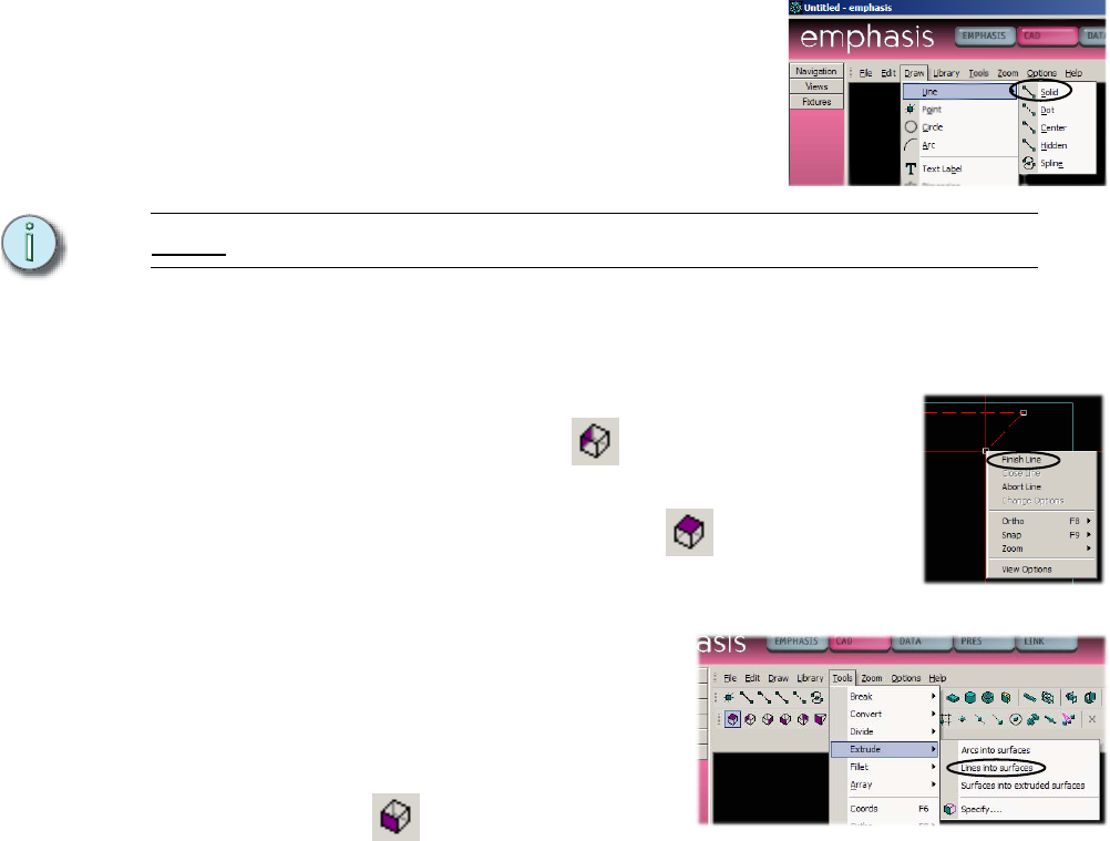
Step 7: Draw a Cyc by extruding a line.
a. In the Draw menu, click Line, then click
Solid.
b. Place the first end of the line at -20’-0”,
14’-0” by moving the mouse to that point
(watch the coordinates display in the
status bar). You can also type “-20’,14’”
ENTER in the ComEdit toolbar.
Note:
You don’t have to click on the ComEdit toolbar, just start typing.
c. Place the other end of the line at 20’-0”, 14’-0” by moving the mouse to that
point (watch the coordinates display in the status bar). You can also type
“20’,14’” ENTER in the ComEdit toolbar.
d. Right-click and select Finish Line.
e. Click on a side view to check the line. It should
appear as a dot on the screen.
f. Click on the Plan View button on the CAD
Options toolbar. Click on the line you drew if it is not
currently selected.
g. In the Tools menu, click
Extrude, then click Lines into
Surfaces.
h. Change the height to 25’-0”
and click OK.
i. Click the Front View button
on the CAD Options
toolbar to see your new cyc.
Step 8: Draw a Border using the Surface tool.
In this step, we’re going to draw a border curtain in the front view. To do this, we
will need to set the “missing coordinate” value to set the upstage/downstage
position of the curtain. The missing coordinate is the dimension you cannot see
in a 2D drawing of a 3D space. In the case of a front view, you can see how wide
and how high an object is, but you cannot see how deep the object is, or how far
upstage or downstage it sits.
a. Change to the front view, if you’re not already there.


