


104 Installing System Components
3
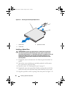
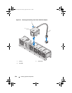
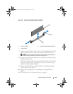
Connect the power cable to the power supply and plug the cable into a
power outlet.
CAUTION: When connecting the power cable, secure the cable with
the Velcro strap.
NOTE: When installing, hot-swapping, or hot-adding a new power supply in a
system with two power supplies, allow several seconds for the system to recognize
the power supply and determine its status. The power-supply status indicator turns
green to signify that the power supply is functioning properly (see Figure 1-7).
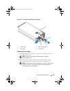
Removing the Power Supply Blank
If you are installing a second power supply, remove the power supply blank
in bay PS2 by pulling outward on the blank.
CAUTION: To ensure proper system cooling, the power supply blank must
be installed in power supply bay PS2 in a redundant configuration. Remove the
power supply blank only if you are installing a second power supply.
Installing the Power Supply Blank
NOTE: Install the power supply blank only in power supply bay PS2.
To install the power supply blank, align the blank with the power supply bay
and insert the blank into the chassis until it clicks into place.
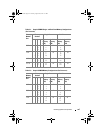
System Memory
Your system supports standard (1.5 V) DDR3 and low voltage (1.35 V)
DDR3L registered DIMMs (RDIMMs) or unbuffered ECC DIMMs
(UDIMMs). Single and dual-rank DIMMs can be 1067 MHz or 1333 MHz,
and quad-rank DIMMs can be 800 MHz or 1067 MHz.
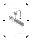
The system contains eight memory sockets split into two sets of four sockets,
one set per processor. Each four-socket set is organized into three channels.
Two DIMMs for channel 0 and a single DIMM for channel 1 and 2. The first
socket of each channel is marked with white release levers.
book.book Page 104 Tuesday, August 24, 2010 1:47 PM