


140 Installing System Components
Control Panel Assembly—LCD (Optional)
NOTE: This section applies to eight–hard-drive systems only.
NOTE: The control panel assembly consists of two separate modules—the display
module and the control panel circuit board. Use the following instructions to
remove and install either module.
Removing the Control Panel Display Module
CAUTION: Many repairs may only be done by a certified service technician.
You should only perform troubleshooting and simple repairs as authorized in
your product documentation, or as directed by the online or telephone service
and support team. Damage due to servicing that is not authorized by Dell is not
covered by your warranty. Read and follow the safety instructions that came
with the product.
1
Turn off the system and attached peripherals, and disconnect the system
from the electrical outlet and peripherals.
2
If applicable, remove the front bezel. See "Removing the Front Bezel" on
page 82.
3
Open the system. See "Opening the System" on page 83.
4
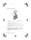
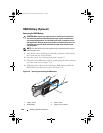
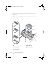
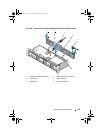
Disconnect the display module cable from the control panel board.
See Figure 3-28.
5
Using a knife or a small flat-blade screwdriver, insert the blade beneath the
front panel of the display and slide the blade across the bottom to lift the
panel outward. See Figure 3-28.
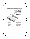
6
Remove the front panel plate until it separates from the display module to
allow access to the mounting screws.
7
Remove the two screws that secure the display module to the system
chassis.
8
Remove the display module from the chassis cutout.
book.book Page 140 Tuesday, August 24, 2010 1:47 PM