


xStack
®
DES-3200-10/18/28/28F Layer 2 Ethernet Managed Switch User Manual
Spanning Tree
This Switch supports three versions of the Spanning Tree Protocol: STP, Rapid STP, and MSTP. STP will be familiar
to most networking professionals. However, since RSTP and MSTP have been recently introduced to D-Link managed
Ethernet switches, a brief introduction to the technology is provided below followed by a description of how to set up
STP, RSTP, and MSTP.
802.1Q-2005 MSTP
Multiple Spanning Tree Protocol, or MSTP, is a standard defined by the IEEE community that allows multiple VLANs
to be mapped to a single spanning tree instance, which will provide multiple pathways across the network. Therefore,
these MSTP configurations will balance the traffic load, preventing wide scale disruptions when a single spanning tree
instance fails. This will allow for faster convergences of new topologies for the failed instance. Frames designated for
these VLANs will be processed quickly and completely throughout interconnected bridges utilizing any of the three
spanning tree protocols (STP, RSTP or MSTP).
This protocol will also tag BPDU packets so receiving devices can distinguish spanning tree instances, spanning tree
regions and the VLANs associated with them. An MSTI ID will classify these instances. MSTP will connect multiple
spanning trees with a Common and Internal Spanning Tree (CIST). The CIST will automatically determine each MSTP
region, its maximum possible extent and will appear as one virtual bridge that runs a single spanning tree.
Consequentially, frames assigned to different VLANs will follow different data routes within administratively
established regions on the network, continuing to allow simple and full processing of frames, regardless of administra-
tive errors in defining VLANs and their respective spanning trees.
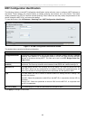
Each switch utilizing the MSTP on a network will have a single MSTP configuration that will have the following three
attributes:
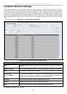
1. A configuration name defined by an alphanumeric string of up to 32 characters (defined in the MST
Configuration Identification window in the Configuration Name field).
2. A configuration revision number (named here as a Revision Level and found in the MST Configuration
Identification window) and;
3. A 4094-element table (defined here as a VID List in the MST Configuration Identification window), which
will associate each of the possible 4094 VLANs supported by the Switch for a given instance.
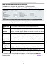
To utilize the MSTP function on the Switch, three steps need to be taken:
1. The Switch must be set to the MSTP setting (found in the STP Bridge Global Settings window in the STP
Version field)
2. The correct spanning tree priority for the MSTP instance must be entered (defined here as a Priority in the
MSTI Config Information window when configuring MSTI ID settings).
3. VLANs that will be shared must be added to the MSTP Instance ID (defined here as a VID List in the MST
Configuration Identification window when configuring an MSTI ID settings).
Rapid Spanning Tree
The Switch implements three versions of the Spanning Tree Protocol, the Multiple Spanning Tree Protocol (MSTP) as
defined by the IEEE 802.1Q-2005, the Rapid Spanning Tree Protocol (RSTP) as defined by the IEEE 802.1D-2004
specification and a version compatible with the IEEE 802.1D-1998 STP. RSTP can operate with legacy equipment
implementing IEEE 802.1D-1998, however the advantages of using RSTP will be lost.
The Rapid Spanning Tree Protocol (RSTP) evolved from the STP standard. RSTP was developed in order to
overcome some limitations of STP that impede the function of some recent switching innovations, in particular, certain
Layer 3 functions that are increasingly handled by Ethernet switches. The basic function and much of the terminology
is the same as STP. Most of the settings configured for STP are also used for RSTP. This section introduces some
new Spanning Tree concepts and illustrates the main differences between the two protocols.
90