


1
MVME55006E Single-Board Computer Installation and Use (6806800A37D)
15
Hardware Preparation and Installation
1.1 Overview
This chapter contains the following information:
z Board and accessory preparation and installation instructions
z ESD precautionary notes
1.2 Introduction
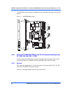
The MVME5500 is a single-board computer based on the PowerPC MPC7457 processor and
the Marvell GT-64260B host bridge with a dual PCI interface and memory controller. On-board
payload includes two PMC slots, two SDRAM banks, an expansion connector for two additional
banks of SDRAM, 8MB boot Flash ROM, one 10/100/1000 Ethernet port, one 10/100 Ethernet
port, 32MB expansion Flash ROM, two serial ports, NVRAM and a real-time clock.
The MVME5500 interfaces to a VMEbus system via its P1 and P2 connectors and contains two
IEEE 1386.1 PCI mezzanine card (PMC) slots. The PMC slots are 64-bit and support both front
and rear I/O.
Additionally, the MVME5500 is user-configurable by setting on-board jumpers. Two I/O modes
are possible: PMC mode or SBC mode (also called 761 or IPMC mode). The SBC mode uses
the IPMC712 I/O PMC and the MVME712M transition module, or the IPMC761 I/O PMC and
the MVME761 transition module. The SBC mode is backwards compatible with the MVME761
transition module and the P2 adapter card (excluding PMC I/O routing) used on the MVME5100
product. This mode is accomplished by configuring the on-board jumpers and by attaching an
IPMC761 PMC in PMC slot 1. Secondary Ethernet is configured to the rear.
PMC mode is backwards compatible with the MVME5100 and is accomplished by configuring
the on-board jumpers.
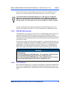
1.3 Getting Started
This section provides an overview of the steps necessary to install and power up the
MVME5500 and a brief section on unpacking and ESD precautions.