


MVME55006E Single-Board Computer Installation and Use (6806800A37D)
Hardware Preparation and Installation Connection to Peripherals
34
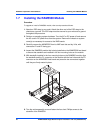
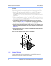
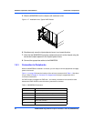
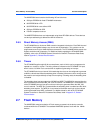
5. Slide the MVME5500 into the chassis until resistance is felt.
6. Simultaneously move the injector/ejector levers in an inward direction.
7. Verify that the MVME5500 is properly seated and secure it to the chassis using the
two screws located adjacent to the injector/ejector levers.
8. Connect the appropriate cables to the MVME5500.
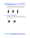
1.9.1 Connection to Peripherals
When the MVME5500 is installed in a chassis, you are ready to connect peripherals and apply
power to the board.
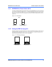
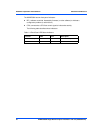
Figure 1-1 on page 20 shows the locations of the various connectors while Table 1-3 lists them
for you. Refer to Chapter 5, Connector Pin Assignments for the pin assignments of the
connectors listed below.
If a PMC module is plugged into PMC slot 1, the memory mezzanine card cannot be used
because the PMC module covers the memory mezzanine connector.
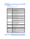
Figure 1-17 Installation into a Typical VME Chassis
Table 1-3 MVME5500 Connectors
Connector Function
J1 COM1 front-panel connector
J2 Dual 1000/100/10BaseT front-panel connectors
J3 IPMC connector
J4 PCI/PMC expansion connector
J5 CPU COP connector
J11, J12, J13, J14 PMC 1 connectors