


Ethernet 2, PMC/SBC Mode, and P2 I/O Selection Headers (J6, J7, J28, J32, J34, J97 – J110) Connector Pin
MVME55006E Single-Board Computer Installation and Use (6806800A37D)
89
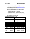
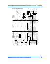
5.3.1.1 Ethernet
Four 3-pin 2 mm planar headers and four 2-pin 2 mm planar headers are for 10/100/BaseT
Ethernet 2 selection. Ethernet 1 is the Gigabit Ethernet port and is front panel only. The
pin assignments for these headers are as follows:
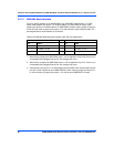
For rear P2 Ethernet, install jumpers across pins 2-3 on all four headers (J6, J7, J100 and
J101). For front-panel Ethernet, install jumpers across pins 1-2 on all four headers.
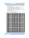
If the rear P2 Ethernet is selected by jumpers J6, J7, J100 and J101, the Ethernet signals also
connect to PMC 1 user I/O connector J14. If a PMC card is plugged into PMC 1, there may be
a conflict between the I/O from the PMC card and the rear Ethernet signals. This conflict does
not occur with the IPMC761 or IPMC712 modules.
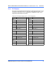
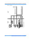
For rear P2 Ethernet, install jumpers on all four headers (J34, J97, J98 and J99) when in
SBC/IPMC761 mode. No jumpers are installed for front-panel Ethernet.
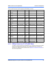
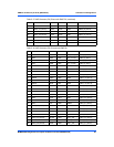
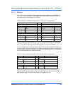
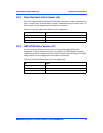
Table 5-20 Ethernet 2 Selection Headers (J6, J7, J100, J101) Pin Assignments
10/100 Ethernet Receive Pairs 10/100 Ethernet Transmit Pairs
J6 J7
Pin Signal Signal Pin
1 FP_RX– FP_TX+ 1
2RX– TX+ 2
3 P2_RX– P2_TX+ 3
J100 J101
1 FP_RX+ FP_TX– 4
2RX+ TX– 5
3 P2_RX+ P2_TX– 6
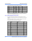
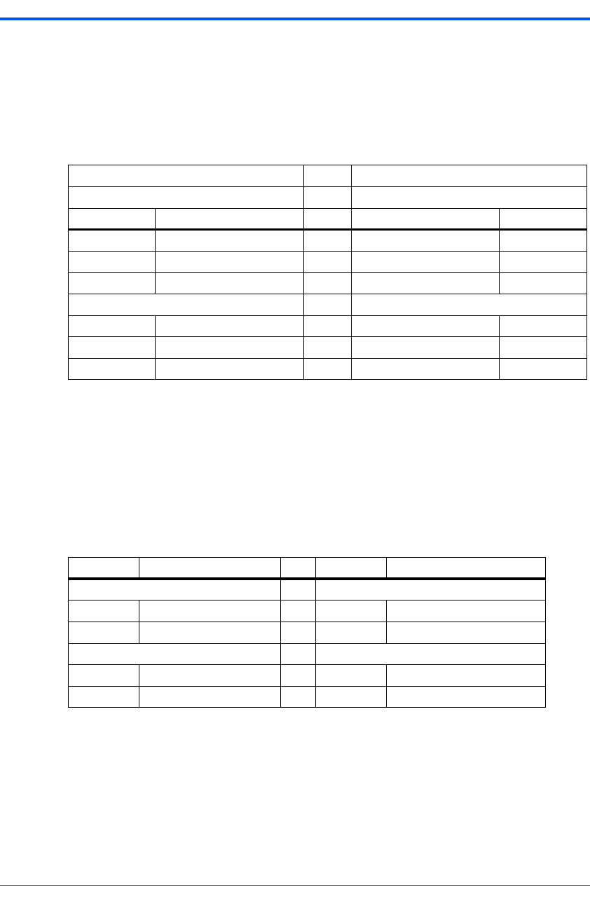
Table 5-21 Ethernet 2 Selection Headers (J34, J97, J98, J99) Pin Assignments
Pin Signal Pin Signal
J34 J97
1 PMC1_IO(7) 1 PMC1_IO (5)
2 P2_TX+ 2 P2_TX-
J98 J99
1 PMC1_IO(3) 1 PMC1_IO (1)
2 P2_RX+ 2 P2_RX-