


System Control and Status Registers Functional Description
MVME55006E Single-Board Computer Installation and Use (6806800A37D)
45
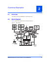
2.12 System Control and Status Registers
The MVME5500 CPU board contains System Control and Status Registers mapped into Bank
1 of the GT-64260B device bus interface. Refer for the MMVE5500 Single-Board Computer
Programmer’s Reference Guide for details.
2.13 Sources of Reset
The sources of reset on the MVME5500 are the following:
z Power-up
z Abort/Reset Switch
z NVRAM Watchdog Timer
z GT-64260B Watchdog Timer
z System Control register bit
z VME Bus Reset
2.14 VME Interface
The MVME5500 provides a Universe II controller for the VMEbus interface.
2.15 PMC Expansion
The MVME5500 provides a PMC expansion connector to add more PMC interfaces than the
two on the MVME5500 board. The connector is a Mictor AMP 767096-3 connector.
2.16 Debug Support
The MVME5500 provides a boundary scan header (J18) and a COP (Riscwatch) header for
debug capability.