


Installing the Board Hardware Preparation and Installation
MVME55006E Single-Board Computer Installation and Use (6806800A37D)
33
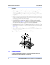
5. Attach the four standoffs from the PMCspanx6E-010 mounting kit to the
PMCspanx6E-002 by screwing the threaded male portion of the standoffs in the
locations where the screws were removed in the previous step.
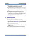
6. Place the PMCspanx6E-010 on top of the PMCspanx6E-002. Align the mounting
holes in each corner to the standoffs and align PMCspanx6E-010 connector P3 with
PMCspanx6E-002 connector J3.
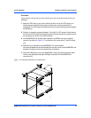
7. Gently press the two PMCspan modules together and verify that P3 is fully seated
in J3.
8. Insert the four screws (Phillips type) through the holes at the corners of
PMCspanx6E-010 and into the standoffs on the primary PMCspanx6E-002. Tighten
screws securely.
The screws have two different head diameters. Use the screws with the smaller
heads on the standoffs next to VMEbus connectors P1 and P2.
You are now ready to install the module into the VME chassis. Follow the procedure, Installing
the Board on page 33.
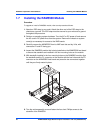
1.9 Installing the Board
Procedure
Use the following steps to install the MVME5500 into your computer chassis.
1. Attach an ESD strap to your wrist. Attach the other end of the ESD strap to an
electrical ground (refer to Unpacking Guidelines). The ESD strap must be secured
to your wrist and to ground throughout the procedure.
2. Remove any filler panel that might fill that slot.
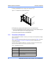
3. Install the top and bottom edge of the MVME5500 into the guides of the chassis.
Only use injector handles for board insertion to avoid damage/deformation to the
front panel and/or PCB.
4. Ensure that the levers of the two injector/ejectors are in the outward position.