


MVME55006E Single-Board Computer Installation and Use (6806800A37D)
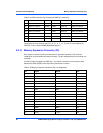
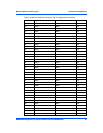
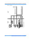
Connector Pin AssignmentsEthernet 2, PMC/SBC Mode, and P2 I/O Selection Headers (J6, J7, J28, J32, J34, J97
90
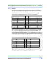
5.3.1.2 PMC/SBC Mode Selection
Two 3-pin planar headers on the MVME5500 are for PMC/SBC mode selection. For PMC
mode, install jumpers across pins 1-2 on both headers. For SBC/IPMC761 mode, install
jumpers across pins 2-3 on both headers. For SBC/IPMC712 mode, install a jumper across pins
2-3 for J32 and install a jumper across pins 1-2 for J28. Selection notes follow the table. The
pin assignments for these headers are as follows:
1. When J28 is configured for SBC/IPMC mode, –12V is supplied to P2 pin A30. If there is an
incompatible board plugged into this P2 slot, damage may occur.
2. When J32 is configured for SBC/IPMC mode, +12V is supplied to P2 pin C7. If there is an
incompatible board plugged into this P2 slot, damage may occur.
3. Install jumpers across pins 1-2 on both headers to select PMC mode. Install jumpers across
pins 2-3 on both headers to select SBC/IPMC761 mode. Install a jumper across pins 2-3
on J32 and install a jumper across pins 1-2 on J28 to select SBC/IPMC712 mode.
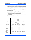
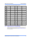
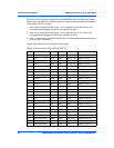
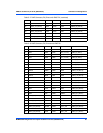
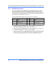
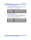
Table 5-22 PMC/SBC Mode Selection Headers (J28, J32) Pin Assignments
J28 J32
Pin Signal Pin Signal
1 Fused –12.0V 1 Fused +12.0V
2 P2_PMC1_IO (60) 2 P2_PMC1_IO (13)
3 PMC1_IO(60) 3 PMC1_IO(13)