


MVME55006E Single-Board Computer Installation and Use (6806800A37D)
Connector Pin Assignments Headers
88
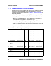
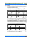
5.3 Headers
This section discusses the various headers associated with the MVME5500.
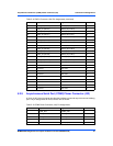
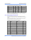
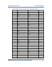
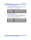
5.3.1 Ethernet 2, PMC/SBC Mode, and P2 I/O Selection Headers (J6,
J7, J28, J32, J34, J97 – J110)
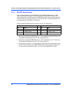
All of the headers described below are used in conjunction with each other to select various
modes of operation for 10/100BaseT Ethernet, PMC/SBC mode and P2 I/O mode.
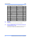
105 MA4 MA3 106
107 MA2 MA1 108
109 +3.3V +3.3V 110
111 MA0 B2_CS# 112
113 B3_CS# GND 114
115 DQM5 DQM7 116
117 SDWE# SDRAS# 118
119 GND GND 120
121 SDCAS# +3.3V 122
123 +3.3V DQM6 124
125 DQM5 I2CSCL 126
127 I2CSDA A1_SPD (GND) 128
129 A0_SPD (NC) DQM4 130
131 DQM3 DQM2 132
133 GND CLK_MEZZ 134
135 GND +3.3V 136
137 DQM1 DQM0 138
139 GND GND 140
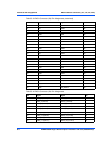
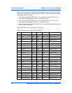
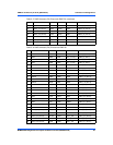
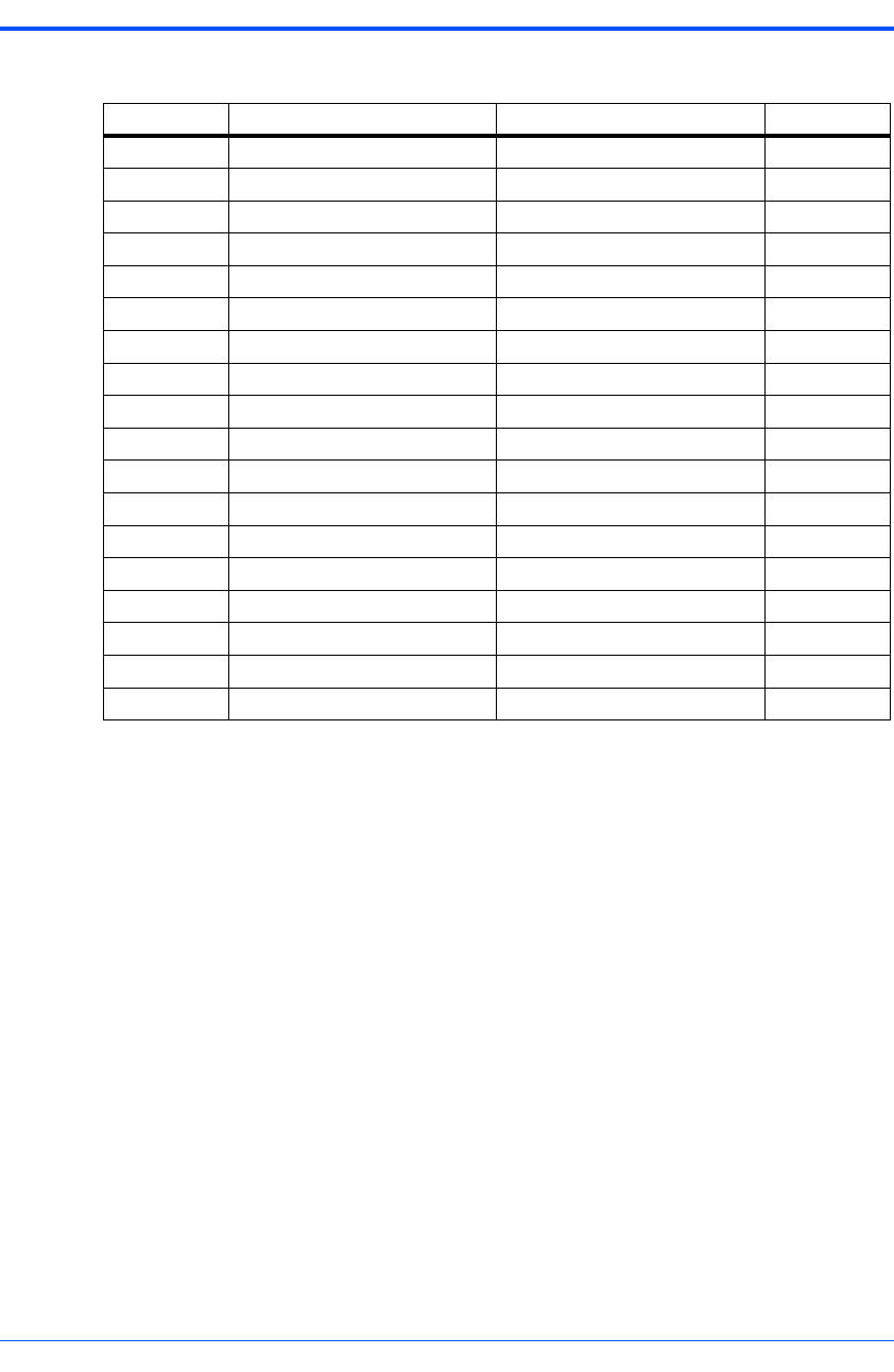
Table 5-19 Memory Expansion Connector (P4) Pin Assignments (continued)
Pin Signal Signal Pin