


MVME55006E Single-Board Computer Installation and Use (6806800A37D)
Functional Description System Memory
42
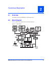
2.8 System Memory
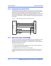
System memory for the MVME5500 is provided by one to four banks of ECC synchronous
DRAM in two banks. During system initialization, the firmware determines the presence and
configuration of each memory bank installed by reading the contents of the serial presence
detection (SPD) EEPROM on the board, and another one on the expansion memory module.
The system firmware then initializes the GT-64260B memory controller for proper operation
based on the contents of the serial presence detection EEPROM.
If a PMC module is plugged into PMC slot 1, the memory mezzanine card cannot be used
because the PMC module covers the memory mezzanine connector.
2.9 PCI Local Buses and Devices
The GT-64260B on the MVME5500 provides two independent 64-bit, 33/66 MHz PCI buses.
The GT-64260B documentation refers to these buses as PCI Bus 0 and PCI Bus 1.
The devices on Bus 1 are the GT-64260B PCI bridge 1, one 32/64-bit PMC slot, and an
825544EI LAN device. The devices on Bus 0 are the GT-64260B PCI bridge 0, one 32/64-bit
PMC slot and a HiNT PCI 6154 PCI-to-PCI bridge. For the purpose of this document, Bus 1 is
also identified as PCI Bus 1.0, and Bus 0 is also identified as PCI Bus 0.0.
2.9.1 Gigabit Ethernet Interface
The MVME5500 provides a Gigabit Ethernet transceiver interface (1000BaseT) using an Intel
82544EI integrated Ethernet device (Ethernet 1). It also supports 100BaseTX and 10BaseT
modes of operation. The Ethernet interface is accessed via an industry-standard, front-panel
mounted RJ-45 connector.
2.9.2 10/100Mb Ethernet Interface
The 10/100Mb Ethernet interface (Ethernet 2) comes from the GT-64260B, and connects to an
external PHY. This port can be routed to a front-panel RJ-45 connector or to the P2 connector
with user-configurable jumpers.
Each Ethernet interface is assigned an Ethernet Station Address. The address is unique for
each device. The Ethernet Station Address is displayed on a label affixed to the board. The
assembly policy is to assign MAC addresses in such a manner that the higher value MAC
address is assigned to Ethernet port 1 and the lower to Ethernet port 2.
In addition, the Gigabit Ethernet address is stored in a configuration ROM interfaced to the
82544EI device, while the 10/100Mb Ethernet address is stored in the on-board VPD serial
EEPROM.