


Primary PMCspan Hardware Preparation and Installation
MVME55006E Single-Board Computer Installation and Use (6806800A37D)
31
Procedure
This procedure assumes that you have read the user’s manual that was furnished with your
PMCspan.
1. Attach an ESD strap to your wrist. Attach the other end of the ESD strap to an
electrical ground. Note that the system chassis may not be grounded if it is
unplugged. The ESD strap must be secured to your wrist and to ground throughout
the procedure.
2. Perform an operating system shutdown. Turn the AC or DC power off and remove
the AC cord or DC power lines from the system. Remove chassis or system cover(s)
as necessary for access to the VME modules.
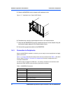
3. If the MVME5500 has already been installed in a VMEbus card slot, carefully
remove it as shown in Figure 1-17 and place it with connectors P1 and P2 facing
you.
4. Attach the four standoffs to the MVME5500. For each standoff:
Insert the threaded end into the standoff hole at each corner of the MVME5500 and
thread the locking nuts into the standoff tips and tighten.
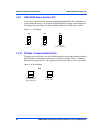
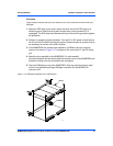
5. Place the PMCspan on top of the MVME5500. Align the mounting holes in each
corner to the standoffs and align PMCspan connector P4 with MVME5100
connector J25.
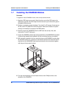
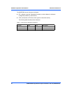
Figure 1-16 PMCspan Installation on a VME Module
2081 9708
PMCspan
MVME5500