


Installing PMCs Hardware Preparation and Installation
MVME55006E Single-Board Computer Installation and Use (6806800A37D)
29
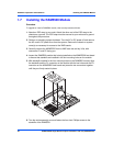
7. Reinstall the MVME5500 assembly in its proper card slot following the procedure in
the next section. Be sure the host board is well seated in the backplane connectors.
Do not damage or bend connector pins.
8. Replace the chassis or system cover(s), reconnect the system to the AC or DC
power source and turn the equipment power on.
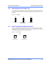
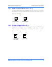
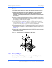
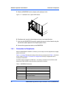
1.8 Installing PMCs
This section discusses the installation of a PMC module onto the MVME5500 and the
installation of a primary and secondary PMCspan module onto the PMC/MVME5500 processor
module.
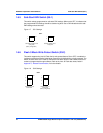
If you have ordered one or more of the optional RAM500 memory mezzanine boards for the
MVME5500, ensure that they are installed on the board prior to proceeding. If they have not
been installed by the factory, and you are installing them yourself, please refer to Installing the
RAM5500 Module on page 28 for installation instructions. It is recommended that the memory
mezzanine modules be installed prior to installing other board accessories, such as PMCs,
IPMCs or transition modules.
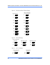
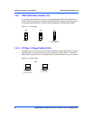
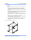
1.8.1 Mounting the PMC Module
PMC modules mount on top of the MVME5500. Perform the following steps to install a
PMCmodule on your MVME5500.
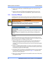
Personal Injury or Death
Dangerous voltages, capable of causing death, are present in this equipment.
Use extreme caution when handling, testing and adjusting.
Product Damage
Inserting or removing modules with power applied may result in damage to module
components.
Avoid touching areas of integrated circuitry, static discharge can damage these
circuits.