


MVME55006E Single-Board Computer Installation and Use (6806800A37D)
Hardware Preparation and Installation Configuring the Board
18
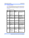
1.6.1 Configuring the Board
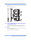
Figure 1-1 illustrates the placement of the jumpers, headers, switches, connectors, and various
other components on the MVME5500. There are several manually configurable headers and
switches on the MVME5500 and their settings are shown in Table 1-2. Each default setting is
enclosed in brackets. For pin assignments on the MVME5500, refer to Chapter 5, Connector
Pin Assignments.
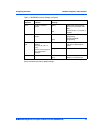
Table 1-2 MVME5500 Jumper Settings
Jumpers /
Switches Function Settings
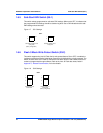
J6, J100, J7,
J101
Ethernet 2 Selection
Headers
(see also J34, J97, J98,
J99)
Refer to the hint on page 7
for a configuration
limitation.
2-3 on all
[1-2 on all]
Rear P2 Ethernet (SBC mode)
Front-panel Ethernet
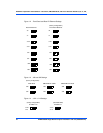
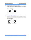
J8 Flash Boot Bank Select
Header
No jumper installed
[1-2]
2-3
Boots from Flash 0
Boots from Flash 0
Boots from Flash 1
S3-1 Flash 0 Programming
Enable Header
OFF
[ON]
Disables Flash 0 writes
Enables Flash 0 writes
S5-1 Safe Start ENV Header [OFF]
ON
Normal ENV settings used
during boot
Safe ENV settings used during
boot
S3-2 Flash 0 Block Write
Protect Header
OFF
[ON]
Disables Flash 0 J3 block
writes
Enables Flash 0 J3 block writes
S3-4 Non-Standard Option
Header
[OFF] For factory use only
S5-2 SROM Initialization
Enable Switch
OFF
[ON]
Enables SROM initialization
Disables SROM initialization
S4-1 PCI Bus 0.0 Speed
Header
[OFF]
ON
PMC board controls whether
the bus runs at 33 MHz or
66 MHz
Forces PCI bus 0.0 to remain at
33 MHz
J27 VME SCON Select
Header
No jumper installed
1-2
[2-3]
Always SCON
No SCON
Auto-SCON
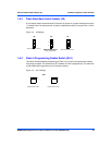
J28, J32 PMC/SBC Mode Selection
Headers
(set both jumpers)
Refer to page 7 for a
notice about configuring
for IPMC mode.
1-2 on both
2-3 on both
[1-2 on J28]
[2-3 on J32]
PMC mode
SBC/IPMC761 mode
SBC/IPMC712 mode