


MVME55006E Single-Board Computer Installation and Use (6806800A37D)
Connector Pin Assignments Memory Expansion Connector (P4)
86
Functionality for rows A and C and Z (Z1, 3, 5, 7, 9, 11, 13, 15, and 17) is provided by the
IPMC761 in slot 1 and the MVME5500 Ethernet port 2.
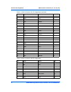
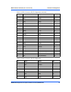
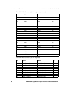
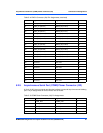
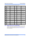
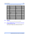
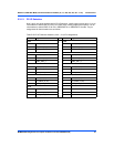
5.2.12 Memory Expansion Connector (P4)
One 140-pin connector is used to provide memory expansion capability. This connector
interfaces to up to two additional banks of memory. The pin assignments for this connector are
as follows:
If a PMC module is plugged into PMC slot 1, the memory mezzanine card cannot be used
because the PMC module covers the memory mezzanine connector.
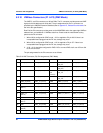
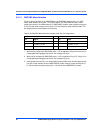
26 GND RXD4 VD27 CTS1_232 PMC2_39 (J24-39)
27 PMC2_41 (J24-41) RTXC4 VD28 TXD2_232 PMC2_40 (J24-40)
28 GND TRXC4 VD29 RXD2_232 PMC2_42 (J24-42)
29 PMC2_44 (J24-44) VD30 RTS2_232 PMC2_43 (J24-43)
30 GND -12VF VD31 CTS2_232 PMC2_45 (J24-45)
31 PMC2_46 (J24-46) MSYNC# GND MDO GND
32 GND MCLK +5V MDI VPC
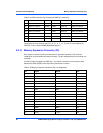
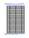
Table 5-18 VME Connector (P2) Pinouts with IPMC761 (continued)
Pin Row Z Row A Row B Row C Row D
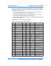
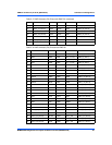
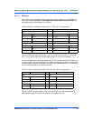
Table 5-19 Memory Expansion Connector (P4) Pin Assignments
Pin Signal Signal Pin
1GND GND 2
3MD0 MD1 4
5MD2 MD3 6
7MD4 MD5 8
9MD6 MD7 10
11 +3.3V +3.3V 12
13 MD8 MD9 14
15 MD10 MD11 16
17 MD12 MD13 18
19 MD14 MD15 20
21 GND GND 22
23 MD16 MD17 24
25 MD18 MD19 26
27 MD20 MD21 28
29 MD22 MD23 30
31 +3.3V +3.3V 32