


Completing the Installation Hardware Preparation and Installation
MVME55006E Single-Board Computer Installation and Use (6806800A37D)
35
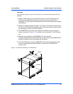
1.9.2 Completing the Installation
Verify that hardware is installed and the power/peripheral cables connected are appropriate for
your system configuration.
Replace the chassis or system cover, reconnect the system to the AC or DC power source, and
turn the equipment power on.
1.10 Startup and Operation
This section gives you information about:
z The power-up procedure
z Switches and indicators
1.11 Applying Power
After you verify that all necessary hardware preparation is complete and all connections are
made correctly, you can apply power to the system.
When you are ready to apply power to the MVME5500:
z Verify that the chassis power supply voltage setting matches the voltage present in the
country of use (if the power supply in your system is not auto-sensing)
z On powering up, the MVME5500 brings up the MotLoad prompt, MVME5500>
1.12 Switches and Indicators
The MVME5500 board provides a single push button switch that provides both Abort and Reset
(ABT/RST) functions. When the switch is depressed for less than three seconds, an abort
interrupt is generated to the processor. If the switch is held for more than three seconds, a
board hard reset is generated.
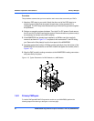
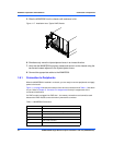
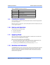
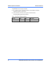
J18 Boundary scan connector
J21, J22, J23, J24 PMC 2 connectors
J33 COM2 planar connector
P1, P2 VME rear panel connectors
P4 Memory expansion connector
Table 1-3 MVME5500 Connectors (continued)
Connector Function