


PMC 1 Interface Connectors (J11, J12, J13, J14) Connector Pin Assignments
MVME55006E Single-Board Computer Installation and Use (6806800A37D)
73
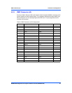
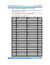
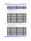
5.2.6 PMC 1 Interface Connectors (J11, J12, J13, J14)
There are four 64-pin SMT connectors for the PMC 1 slot on the MVME5500 to provide a 32/64-
bit PCI interface and optional I/O interface.
If a PMC module is plugged into PMC slot 1, the memory mezzanine card cannot be used
because the PMC module covers the memory mezzanine connector.
Table 5-6 PMC 1 Connector (J11) Pin Assignments
Pin Signal Signal Pin
1 TCK –12V 2
3GND INTA# 4
5INTB# INTC# 6
7 PRESENT# +5V 8
9 INTD# PCI_RSVD 10
11 GND +3.3Vaux 12
13 CLK GND 14
15 GND GNT#/XREQ0# 16
17 REQ#/XGNT0# +5V 18
19 VIO AD31 20
21 AD28 AD27 22
23 AD25 GND 24
25 GND C/BE3# 26
27 AD22 AD21 28
29 AD19 +5V 30
31 VIO AD17 32
33 FRAME# GND 34
35 GND IRDY# 36
37 DEVSEL# +5V 38
39 GND LOCK# 40
41 PCI_RSVD PCI_RSVD 42
43 PAR GND 44
45 VIO AD15 46
47 AD12 AD11 48
49 AD09 +5V 50
51 GND C/BE0# 52
53 AD06 AD05 54
55 AD04 GND 56
57 VIO AD03 58
59 AD02 AD01 60