


DXP DVI Pro and DXP HDMI Series • Operation 12
• Room — A subset of outputs that are logically related to each other, as determined
by the operator. The switchers support up to 10 rooms, each of which can consist of 1
to 16 outputs. Each room can have up to 10 presets.
• Room memory preset — A configuration consisting of outputs in a single room
that has been stored. When a room preset is retrieved from memory, it becomes the
current configuration for the outputs assigned to that room only (none of the other
outputs are affected).
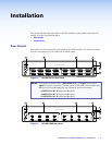
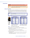
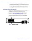
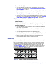
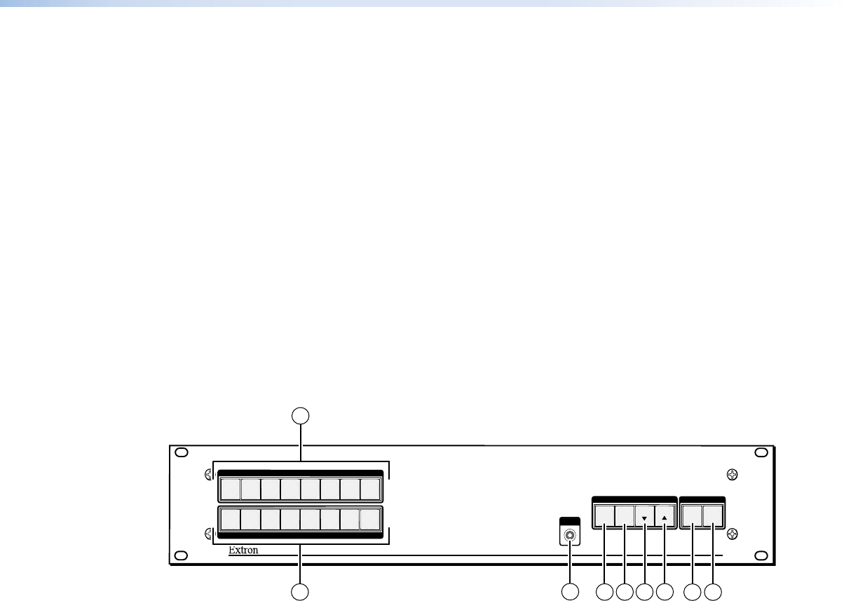
Front Panel Controls and Indicators
All models of the DXP have the same front panel with the same controls and layout. The
front panel buttons are grouped into two sets, with the input and output buttons located
on the left side of the control panel and the control buttons on the right.
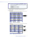
These illuminated push buttons can be labeled with text or graphics. You can set the
buttons to have amber background illumination all the time, or you can disable the
illumination (see “Setting the Button Background Illumination” on page 42).
Depending on the operation, the buttons blink or light steadily when pressed.
The front panel buttons have multiple functions. In the descriptions on the following
pages, primary functions are preceded by a square (❏) and secondary functions are
preceded by a bullet (
•
).
DXP SERIES
DIGITAL CROSSPOINT MATRIX SWITCHER
CONTROL
ENTER PRESET
VIEW ESC
INPUTS
1
2
3
4
5
6
7
8
1
2
3 4
5
6
7
8
OUTPUTS
CONFIG
1
2
3
654
7
I/O
VIDEO
AUDIO
8
9
Figure 10. DXP Switchers Front Panel