


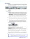
DSP Signal Chain
The DSP signal chain is in a fixed order and each processor block inserts only one category
of processor. However, the signal chain is also exible in that a variety of processor types
can be inserted per processor category.
Processor blocks are placed in the signal chain pre- and post-switcher to perform specific
tasks. There are level control blocks, signal processor blocks, and mix-point blocks (with
level control).
Processor blocks
Processor blocks, though performing different functions, have several common elements.
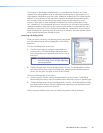
z Insert — All blocks (except level controls) may be inserted by right-clicking on the
desired box and selecting from the context menu or by double-clicking and selecting.
z Remove a process — Active processors can be removed by right-clicking on the
box and selecting Delete or by selecting the block and pressing <Delete> on the
keyboard. An active processor may be replaced by right-clicking and inserting a new
processor. A warning will appear to indicate the previous processor is about to be
replaced.
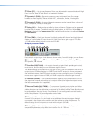
z Mute — When a level block (gain, trim or volume) is muted, all signal ow is blocked.
When mute is active a red mark appears in the lower left of the block. Mix-point mute
is indicated by shadowing the mix-point.
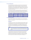
z Bypass — When bypass is active, signal ow passes through the block without
processing, regardless of the settings. When bypass is removed, the signal will be
processed according to the parameter settings. A red mark appears in the lower left of
the block (shown below) to indicate it has been inserted, but is currently bypassed.
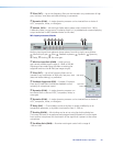
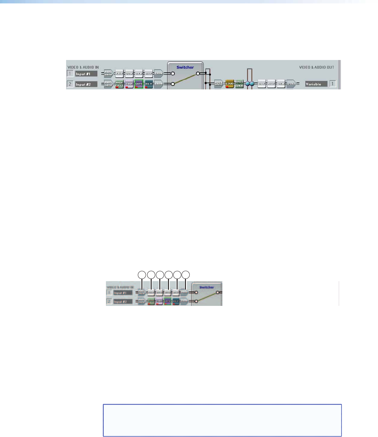
Line input processor blocks
3
2
1
6
54
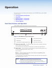
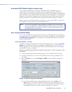
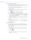
Pre-switcher input signal chain elements shown above, from left to right, are as follows:
a
Gain,
b
Filter,
c
Dynamics (1),
d
Dynamics (2),
e
Delay,
f
Trim
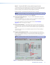
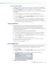
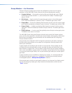
a Gain (GAIN) — Each line input channel GAIN block opens a Stereo Line Gain dialog,
with the exception of input 4, which opens a Mono Line Gain dialog. The Stereo Line Gain
dialog provides stereo left-channel and right-channel faders. The Mono Line Gain dialog
provides a mono fader. Each fader control has a range of -18 dB to +24 dB and a level
setting text field is located below the fader.
Left-channel and right-channel Mute buttons independently mute the left and right
channels to the stereo bus. As a mono channel, the input 4 Mono Line Gain dialog has a
single Mute button.
NOTE: • Inputs 1 through 4 are analog (ANG GAIN block).
• Inputs 5 through 8 are digital (DIG GAIN block) but can be congured to
accept either a digital (default) or an analog 2-channel input stream.
• Input 4 is a mono input.
MLS 608 D Series • Operation 28