


Building Blocks — An Overview
Extron building blocks are a quick conguration tool that can signicantly reduce device
configuration time. A building block is a collection of processor and gain settings for a
particular portion of the signal chain. This allows configuration of an entire mic input, line
input, or line output channel with just two clicks.
A comprehensive set of pre-configured building blocks is placed on your computer system
as you install DSP Configurator. If you are new to DSP processing, these building blocks
may give you all that you need for complete conguration of your Extron DSP product.
The pre-configured building blocks can also be used as a starting point, giving you a
basic device setup while staging an installation, then fine-tuning the system during
commissioning in the eld. Building blocks can be modied, then saved, allowing you to
create a customized set of tools unique to your needs. Alternatively, building blocks can be
built from a blank screen or an existing configuration, allowing you total flexibility in how
you create and deploy this useful and time saving feature.
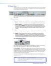
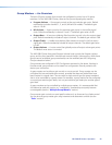
Microphone building blocks
Extron building blocks for microphones set the gain level for a specic brand name
and model, and turn on phantom power if required for that mic. An high pass filter is
inserted to compensate for common microphone problems such as low frequency noise
(thumping) or "plosives" (popping). A bass and treble shelving filter is also inserted into
the lter block, with gain level set to 0 dB. This allows adjustment of the microphone
tone, if necessary, either via the DSP Configurator software or by programming the gain
parameters into a control system and allowing the user to make adjustments. Finally, a
compressor is inserted into a dynamics processing block, applying light compression to
the channel for the purpose of both normalizing diverse signal levels and protecting the
system. Compressor threshold is set at -12 dBFS with soft knee control added, with a 2:1
compression ratio. The compressor threshold is above target level so as not to affect unity
gain (at the target level) through the system.
Gain levels used are based on several factors:
z Reference sound pressure level (SPL) level (from the talker) at 1 meter
z Distance of talker from microphone
z Microphone sensitivity (provided by the manufacturer)
z Target channel level
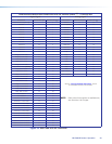
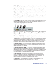
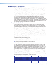
The table below shows different microphone categories, the reference SPL level at the
mic (talker level), mic distance used for that category, and the target channel level. The
reference SPL level used accounts for a heightened level produced by a loud talker at 74
dBSPL (based on 65 dBSPL to 68 dBSPL being a normal talking level at 1 meter). A loud
talker level was chosen to ensure that all microphone inputs have sufficient headroom.
The target channel level is +4 dBu, which allows for sufcient headroom. +4 dBu on the
channel displays a meter level of -17 dBFS. Given the maximum output level of +21 dBu
for the device, 0 dBFS is equal to +21 dBu. Therefore a level of -17 dBFS equals +4 dBu
(+21 dBu - 17 dB = +4 dBu). When the target level is achieved at the input, maintaining
unity gain through the system produces +4 dBu at the output.
Microphone Type Reference Level Source Distance Target Level
Lectern - Goosenecks 74 dBSPL 1 foot -17 dBFS (+4 dBu)
Table Mics - Boundary 74 dBSPL 2 feet -17 dBFS (+4 dBu)
Table Mics - Goosenecks 74 dBSPL 2 feet -17 dBFS (+4 dBu)
Ceiling Mics 74 dBSPL 5 feet -17 dBFS (+4 dBu)
Handheld Mics 74 dBSPL 0.5 feet -17 dBFS (+4 dBu)
MLS 608 D Series • Operation 31