


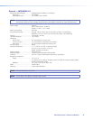


Input gain adjustment
Mic/line input .......................... -18 dB to +80 dB, adjustable per input
All other inputs ........................ -18 dB to +24 dB, adjustable per input
Mic phantom power ....................... +48 VDC (can be switched on or off)
NOTE: 0 dBu = 0.775 Vrms, 0 dBV = 1 Vrms, 0 dBV ≈ 2 dBu.
Audio output — line level (all models) — MLS
Number/signal type ........................ 2 stereo or dual mono, balanced/unbalanced (fixed or variable, selectable)
1 dual mono, balanced/unbalanced (fixed or variable, selectable), via MTP
Connectors .................................... (2) 3.5 mm captive screw connectors, 5 pole
Impedance ..................................... 50 ohms unbalanced, 100 ohms balanced
Gain error ...................................... ±0.2 dB channel to channel
Nominal level ................................. +4 dBu (1.23 Vrms)
Maximum level (Hi-Z) ...................... >+21 dBu, balanced; >+15 dBu, unbalanced
NOTE: Unbalanced wired outputs have -6 dB gain. Balanced outputs result in a 0 dB gain.
Audio output — power amplier (amplier models only) — MLS
Number/signal type
MA model ............................... 1 mono, 70 V line
SA model ................................. 1 stereo (default) or 2 mono, 2 channels total
Connector ...................................... (1) 5 mm screw lock captive screw connector, 4 pole
NOTE: These connectors accept wires of 22 AWG to 12 AWG.
Load impedance
MA model ............................... 123 ohms minimum
SA model ................................. 4 or 8 ohms
Amplifier type ................................ Class D
Output power
MA model ............................... 40 watts (rms), 70 V, 1 kHz, 1% THD
SA model ................................. 20 watts (rms) per channel, 4 or 8 ohms, 1 kHz, 1% THD
Protection ...................................... Clip limiting, thermal, short circuit, DC output
Control/remote — switcher — MLS
NOTE: The front panel USB port and rear panel RS-232 port are independent of each other and can be used at the
same time.
Serial control port ........................... 1 bidirectional RS-232: 1 rear panel 3.5 mm captive screw connector, 5 pole
(uses 3 poles)
Baud rate and protocol ................... 300 to 115200 baud (38400 baud = default); 8 (default) or 7 data bits; 1 (default) or
2 stop bits; no parity (default), or even, odd, mark, or space parity; no flow control
(default)
Serial control pin configuration ....... 1 = Tx, 2 = Rx, 3 = GND, 4 = neutral/GND, 5 = +12 VDC
NOTE: Protocol is mirrored between the MLS 608 D and the MTP/HDMI U R receiver.
Serial control pin configuration ....... Captive screw connector: 1 = Tx, 2 = Rx, 3 = GND, 4 = n/a, 5 = n/a
NOTE: The +12 VDC and ground pins can be used to power a MediaLink
®
Controller.
USB control ports ........................... 1 front panel female mini USB B
USB standards ................................ USB 2.0, low speed
Program control ............................. Extron DSP Congurator
™
software for Windows
®
Extron Simple Instruction Set (SIS
™
)
Control/remote — external device (pass-through) — MLS
Serial control port input .................. Bidirectional RS-232 via (1) 3.5 mm captive screw connector, 5 pole (uses 3 poles)
Serial control port output ............... 1 set of proprietary signals on a female RJ-45 jack
MLS 608 D Series • Reference Material 87