


RESTRICTED USE ONLY FARGO Electronics, Inc.
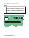
Determining the Magnetic Card Offset (process description)
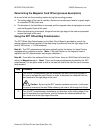
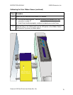
As a card is fed into the encoding module during the encoding process:
a. The trailing edge of the card is read by a Sensor and continues to feed for a given length
of a standard CR-80 sized card,
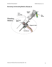
b. The direction of the feed Motor is reversed and the magnetic data string begins to encode
onto the Magnetic Stripe of the card.
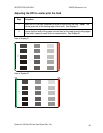
c. When the data string is encoded, it begins from the right edge of the card and proceeds
across the length of the card.
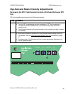
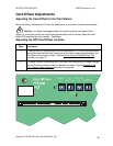
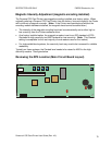
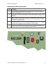
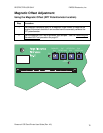
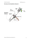
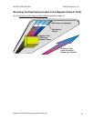
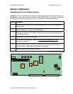
Using the RP7 Offset Mag Potentiometer
The RP7 Offset Mag Potentiometer on the Main Circuit Board is provided to control the
precise distance the start sentinel of the data string is positioned from the right edge of the
card (0.293 inches, +/- 0.020 tolerance).
Note #1: The RP7 potentiometer has been originally set by the factory for those Printers
equipped with a magnetic encoder. (Note: If the card Sensor or the magnetic head is
replaced, the RP7 potentiometer may require calibration.)
Note #2: From within the software Driver for the Printer, there is a Shift Data Left check box
within the Magnetics option. (Note: This is not the same adjustment provided by the RP7
potentiometer; it is an option used to shift to the data left side of the card for use in insertion
card readers.)
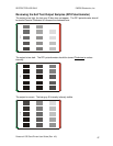
Step Procedure
1 Turn the RP7 potentiometer counter-clockwise (so more of the trailing edge of
the card is fed past the card Sensor) in order to decrease the distance from the
start sentinel to the right edge of the card.
Caution: By turning the RP7 counter-clockwise too much, it will cause
the card to overshoot the feed Roller allowing the card to fall through the Printer.
2 Turn the RP7 potentiometer clockwise to (a) allow less of the trailing edge of the
card to feed past the card Sensor, and (b) increase the distance between the
start sentinel and the right edge of the card.
Persona® C25 Card Printer User Guide (Rev. 4.0)
73