5-3
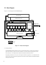
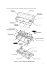
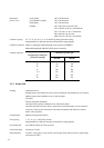
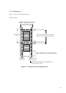
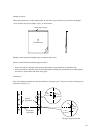
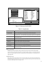
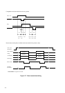
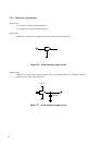
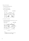
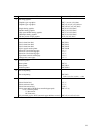
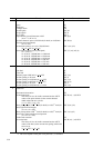
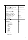
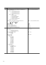
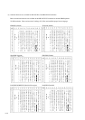
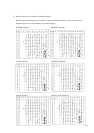
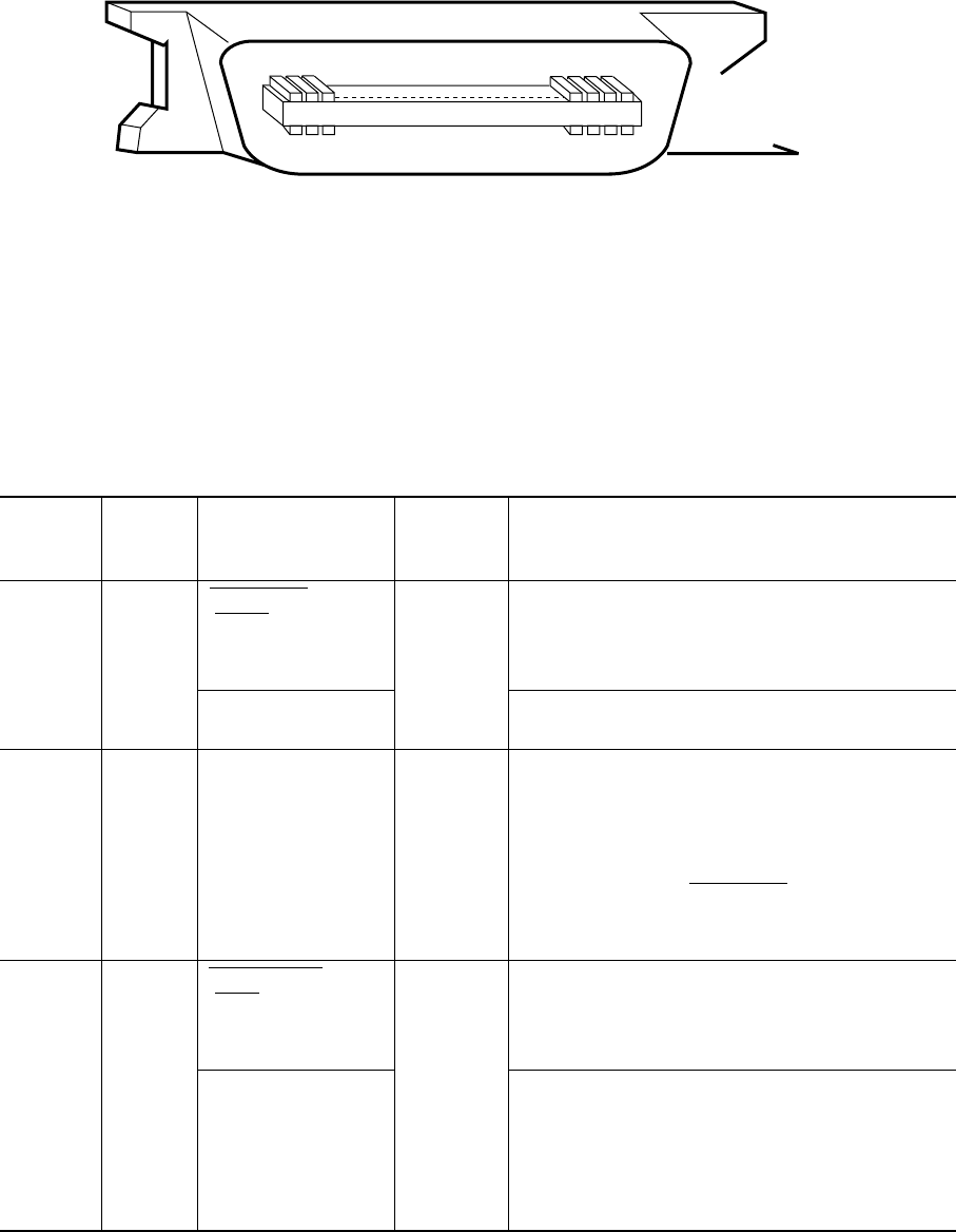
Figure 5.4 Parallel interface connector
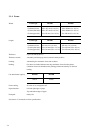
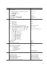
Return
line pin
number
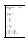
19
20
21
22
23
24
25
26
27
28
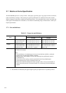
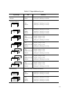
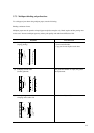
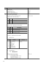
Signal
Compati mode
Nibble mode
Data Strobe
(DSTB)
Host Clock
Data 1
Data 2
Data 3
Data 4
Data 5
Data 6
Data 7
Data 8
Acknowledge
(ACK)
Printer Clock
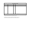
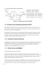
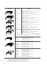
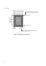
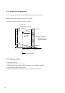
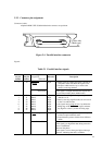
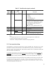
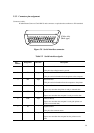
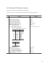
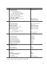
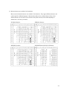
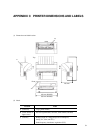
5.2.2 Connector pin assignment
Connector (cable):
Amphenol DDK 57FE-30360 shielded male connector or equivalent
(Cable side)
(Male type)
36
18
1
19
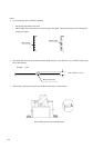
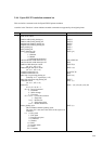
Description
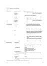
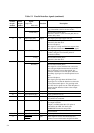
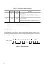
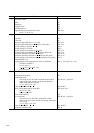
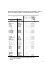
• Strobe pulse for reading data (Data 1 to Data 8).
The printer reads data when this signal is low.
• The pulse width must be 1 µs or more at the
printer’s receiving terminal.
This signal is set high when the host requests the
reverse data transfer phase (nibble mode).
• Data 1 to Data 8 signals correspond to parallel
data bits 1 to 8.
• Data 8 is the most significant bit, but is not used
in the 7-bit ASCII mode.
• All signals must go high at least 1 µs before the
falling edge of the Data Strobe signal, and must
stay high for at least 1 µs after the rising edge.
• Pulse signal indicating data reception completed
(or data reception enabled) status
• Issued when the printer switches from offline to
online
Reverse data transfer phase:
This signal goes high when data being sent to the
host is established.
Reverse idle phase:
This signal is set low then goes high to interrupt
the host, indicating that data is available.
Connec-
tor pin
number
1
2
3
4
5
6
7
8
9
10
Signals:
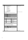
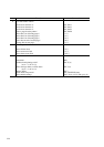
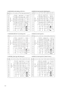
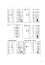
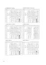
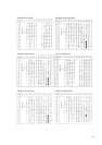
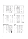
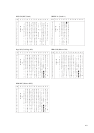
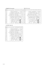
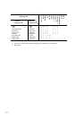
Table 5.1 Parallel interface signals
Direction
Input
Input
Input
Input
Input
Input
Input
Input
Input
Output