


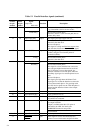
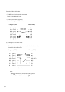
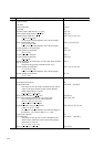
5-12
TD
RD
DSR
DTR
RTS
CTS
CD
SG
TD
RD
DSR
DTR
RTS
CTS
CD
SG
(pin 2)
(pin 3)
(pin 6)
(pin 20)
(pin 4)
(pin 5)
(pin 8)
(pin 7)
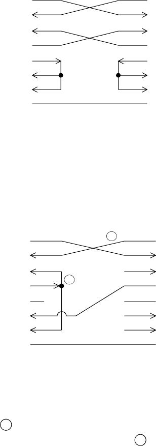
Computer (DTE) Printer (DTE)
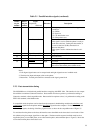
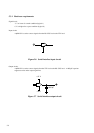
Example of cable configuration:
• To DCE (data circuit terminating equipment)
Use the “straight-through” cable.
• To DTE (data terminal equipment)
Use the “cross-patched” cable below.
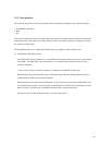
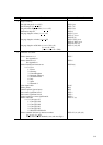
(2) Full-duplex 3-wire control mode
This mode enables more simple communication than the above mode.
Example of cable configuration:
Notes:
1. Wire 1 is not necessary for the DTR (or RC) protocol.
2. Some computers may not require wire 2 .
TD
RD
DSR
DTR
RTS
CTS
CD
SG
TD
RD
DSR
DTR (RC)
RTS
CTS
CD
SG
(pin 2)
(pin 3)
(pin 6)
(pin 20)
(pin 4)
(pin 5)
(pin 8)
(pin 7)
Computer (DTE) Printer (DTE)
#
#
#
#
#
# Open wire
2
1