


5-11
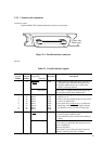
5.3.4 Timing diagram and cable configuration
The printer enables or disables input control signals for the printer linked with the RS-232C interface, enabling
communication via the RS-232C interface as well as more simple communication.
There are mainly two ways to connect the RS-232C interface:
• Full-wire
• 3-wire
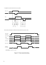
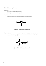
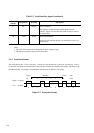
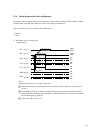
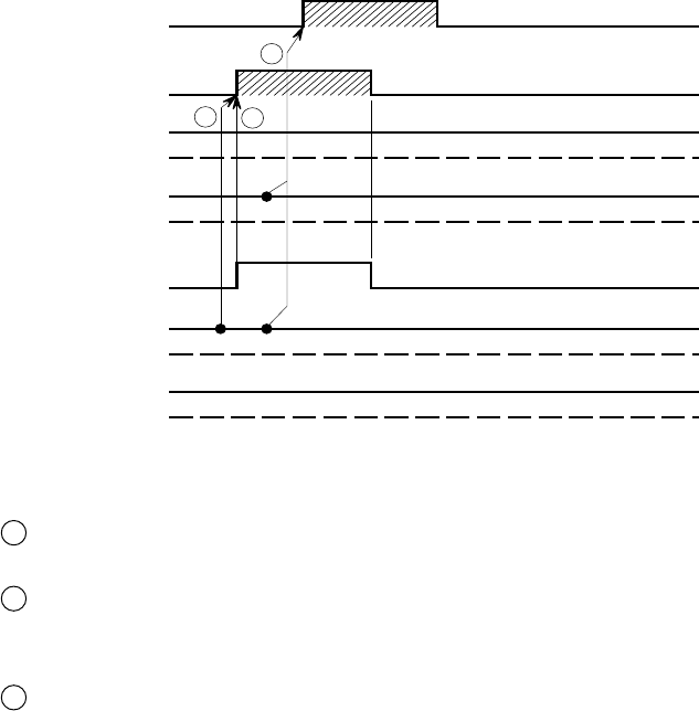
(1) Full-duplex full-wire control mode
Timing diagram:
Notes:
Signals prefixed by a dot (.) are input to the printer.
1 DSR must be high (on) when the printer receives data in this mode. Otherwise, received data is
ignored.
2 If both DSR and CTS are on when the printer has data to be transmitted to the computer in this
mode, the printer transmits the data immediately. If either DSR or CTS is off, data is not transmit-
ted until both signals go high (on).
3 In this mode, CD is “don’t care.”
TD
.RD
RTS
.CTS
.CD
.DSR
DTR
(pin 2)
(pin 3)
(pin 4)
(pin 5)
(pin 8)
(pin 6)
(pin 20)
On
OnOn
On
Space
Mark
Space
Mark
On
Off
On
Off
On
Off
On
Off
On
Off
2
3
1