


5-9
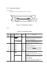
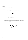
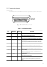
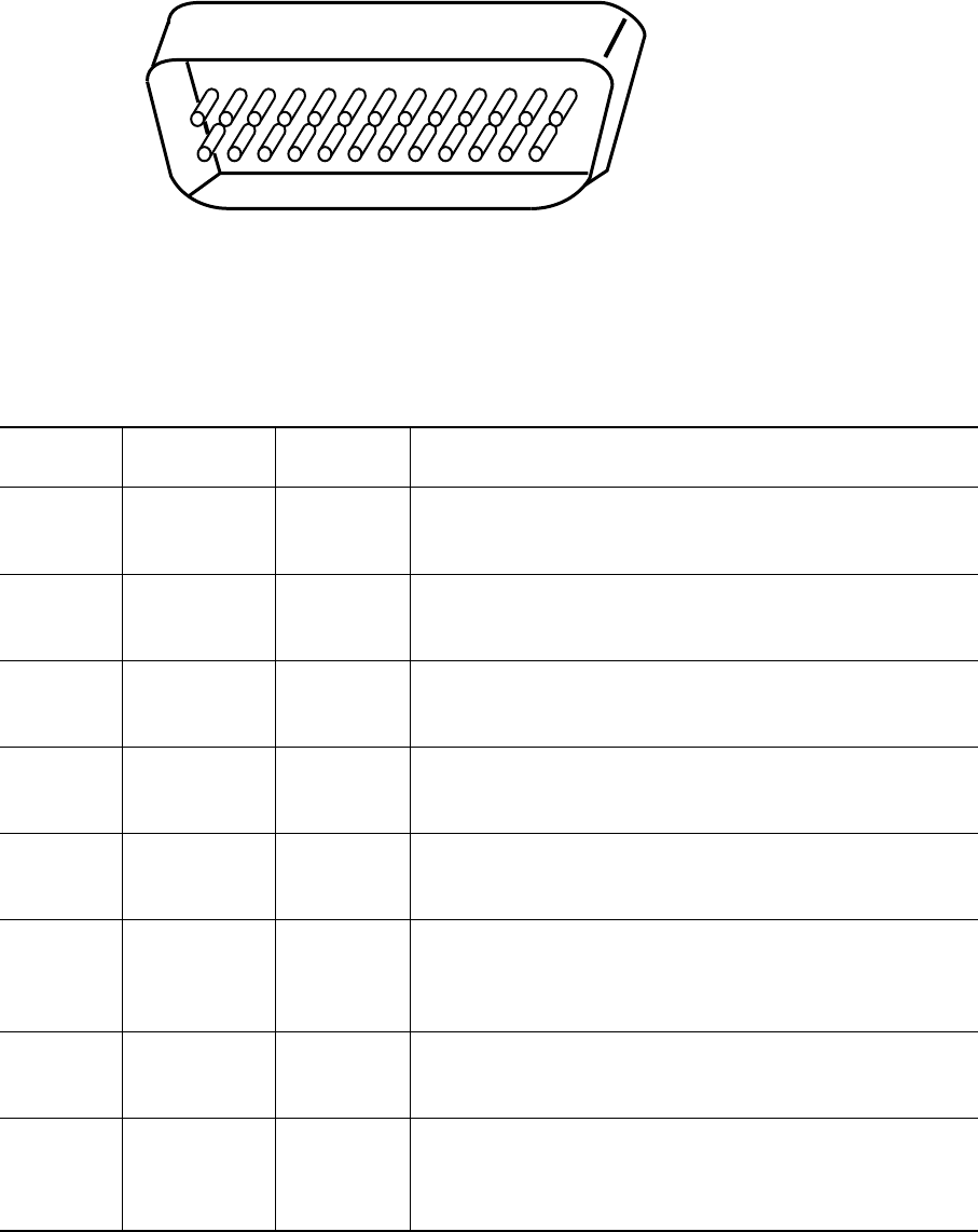
5.3.2 Connector pin assignment
Connector (cable):
D-subminiature Canon or Cinch DB-25 male connector or equivalent that conforms to EIA standards
Figure 5.8 Serial interface connector
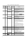
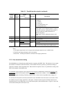
Table 5.2 Serial interface signals
Pin
number
1
2
3
4
5
6
7
8
Description
Frame/chassis Ground
This pin is the safety/protective ground.
Transmitted Data
This pin carries information from the printer to the computer.
Received Data
This pin carries information from the computer to the printer.
Request to Send
Spaces are sent when the printer is ready to transmit data.
Clear to Send
Spaces are sent when the computer is ready to receive data.
Data Set Ready
Spaces are sent when the computer is ready (the printer can
receive or transmit data).
Signal Ground
This pin is the common return.
Carrier Detect
Spaces are sent when the computer lets the printer receive
data.
Designation
FG
TD
RD
RTS
CTS
DSR
SG
CD
Direction
–
Output
Input
Output
Input
Input
–
Input
(Cable side)
(Male type)
1
14
13
25