


Features of the IBP Module Introduction
Intelligent Blade Panel Module
23
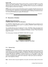
2.2.2 Status of LEDs
The front panel contains light emitting diodes (LED) that indicate the status of links, and IBP
diagnostics.
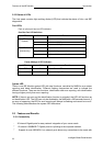
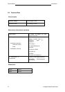
Port LEDs
Each of uplink port has two LED indicators.
One Gbe Port LED definition:
LED Color Function
Orange Port Link at 1000 Mbps
Green Port Link at 100 Mbps
LED-A
(Speed)
Off Port Link at 10 Mbps
Yellow Network Link
Yellow Blink Network Activity
LED-B
(Link/Activity)
Off No Network Link or port disable
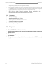
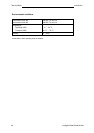
Power, Manage of LED indicator:
LED Color Function
TOP Green Power LED
BUTTOM
Green Identify LED
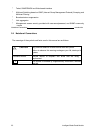
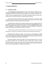
System LED
There is one IBP Module system LED with dual functions, controlled by MMB for error status
reporting and blade identification. Different flashing frequencies are used to indicate the
different functions. There are two functions, identification and error reporting, with identification
having a higher priority than error reporting.
NOTE: If there is an error and the identification function is activated, the LED still functions as
an identification LED. The LED can only be disabled by the MMB with a 255 seconds timeout. If
an error is happening, the LED for error reporting will always be flashing and cannot be turn off.
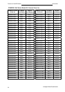
The following table describes the system LED indications.
2.3 Features and Benefits
2.3.1 Connectivity
l
30
internal
Gigabit
ports
for
easy
network
integration
of
your
server
cards
l
12
external
1000BASE-T
Gigabit
ports
for
uplinking
to
the
corporate
network
l
Support
for
auto
MDI/MDI-X
on
external
ports
allows
any
connections
to
be made
with