


C141-E090-01EN 5 - 85
5.6 Timing
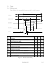
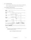
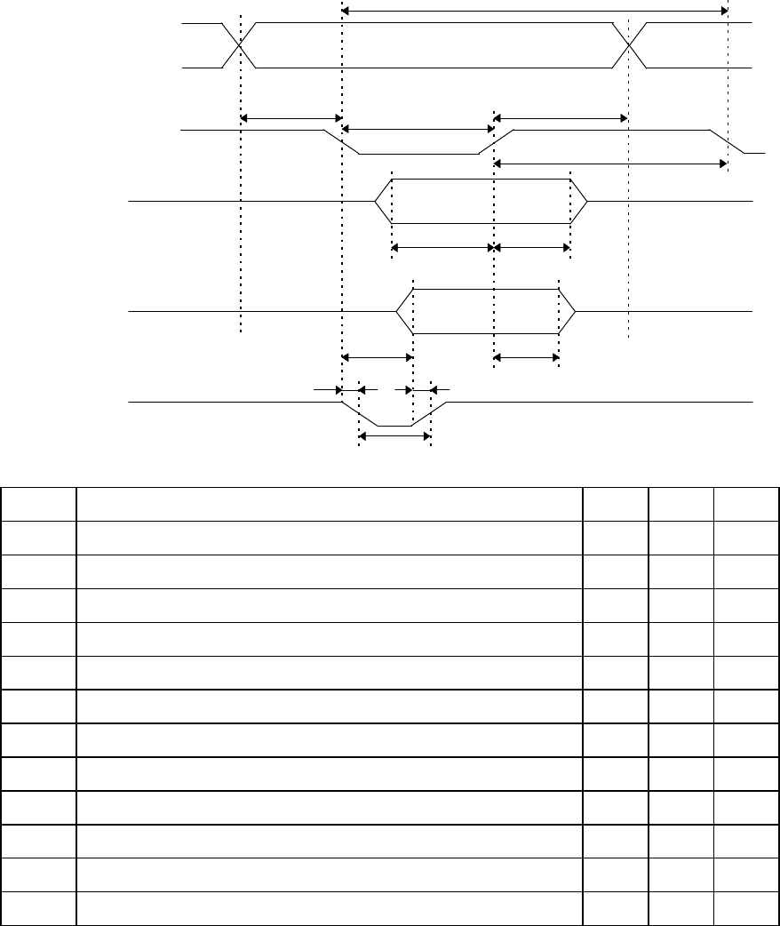
5.6.1 PIO data transfer
Figure 5.8 shows of the data transfer timing between the device and the host system.
t6
t12
t11t10
t5
t4t3
t9
t2i
t2
t1
t0
Addresses
IORDY
Read data
DD0-DD15
Write data
DD0-DD15
DIOR-/DIOW-
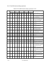
Symbol Timing parameter Min. Max. Unit
t0 Cycle time 120 — ns
t1 Data register selection setup time for DIOR-/DIOW- 25 — ns
t2 Pulse width of DIOR-/DIOW- 70 — ns
t2i Recovery time of DIOR-/DIOW- 25 — ns
t3 Data setup time for DIOW- 20 — ns
t4 Data hold time for DIOW- 10 — ns
t5 Time from DIOR- assertion to read data available — 50 ns
t6 Data hold time for DIOR- 5 — ns
t9 Data register selection hold time for DIOR-/DIOW- 10 — ns
t10 Time from DIOR-/DIOW- assertion to IORDY "low" level — 35 ns
t11 Time from validity of read data to IORDY "high" level 0 — ns
t12 Pulse width of IORDY — 1,250 ns
Figure 5.8 PIO data transfer timing