


C141-E090-01EN5 - 4
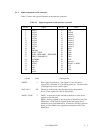
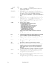
[signal] [I/O] [Description]
DIOR– I DIOR– is the strobe signal asserted by the host to read device
registers or the data port.
HDMARDY– I HDMARDY– is a flow control signal for Ultra DMA data in
bursts. This signal is asserted by the host to indicate to the device
that the host is ready to receive Ultra DMA data in bursts.
The host may negate HDMARDY- to pause an Ultra DMA data in
burst.
HSTROBE I HSTROBE is the data out strobe signal from the host for an Ultra
DMA data out burst. Both the rising and falling edge of
HSTROBE latch the data from DATA 0-15 into the device. The
host may stop generating HSTROBE edges to pause an Ultra
DMA data out burst.
INTRQ O Interrupt signal to the host.
This signal is negated in the following cases:
– assertion of RESET– signal
– Reset by SRST of the Device Control register
– Write to the command register by the host
– Read of the status register by the host
– Completion of sector data transfer
(without reading the Status register)
When the device is not selected or interrupt is disabled, the
INTRQ
Signal shall be in a high impedance state.
CS0– I Chip select signal decoded from the host address bus. This signal
is used by the host to select the command block registers.
CS1– I Chip select signal decoded from the host address bus. This signal
is used by the host to select the control block registers.
DA 0-2 I Binary decoded address signals asserted by the host to access task
file registers.
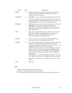
KEY – Key pin for prevention of erroneous connector insertion
PIDAG– I/O This signal is an input mode for the master device and an output
mode for the slave device in a daisy chain configuration. This
signal indicates that the slave device has been completed self
diagnostics.
This signal is pulled up to +5 V through 10 kΩ resistor at each device.
CBLID– I/O This signal is used to detect the cable type (80 or 40-conductor
cable) installed in the system. This signal is pulled up to +5 V
through 10 kΩ resistor at each device.
DASP– I/O This is a time-multiplexed signal that indicates that the device is
active and a slave device is present.
This signal is pulled up to +5 V through 10 kΩ resistor at each device.