


C141-E090-01EN 3 - 3
3.2 Mounting
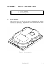
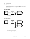
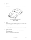
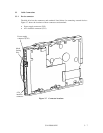
(1) Orientation
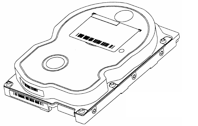
Figure 3.2 illustrates normal orientation for the disk drive. The disk drives can be mounted in
any orientation.
Horizontal mounting with the PCB facing down
Figure 3.2 Orientation
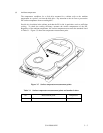
(2) Frame
The disk enclosure (DE) body is connected to signal ground (SG) and the mounting frame is
also connected to signal ground. These are electrically shorted.
Note:
Use No.6-32UNC screw for the mounting screw and the screw length should satisfy the
specification in Figure 3.4.
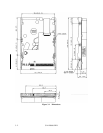
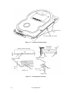
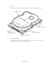
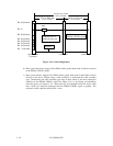
(3) Limitation of side-mounting
When the disk drive is mounted using the screw holes on both side of the disk drive, use two
screw holes shown in Figure 3.3.
Do not use the center hole. For screw length, see Figure 3.4.