


C141-E090-01EN5 - 6
5.2 Logical Interface
The device can operate for command execution in either address-specified mode; cylinder-
head-sector (CHS) or Logical block address (LBA) mode. The IDENTIFY DEVICE
information indicates whether the device supports the LBA mode. When the host system
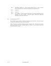
specifies the LBA mode by setting bit 6 in the Device/Head register to 1, HS3 to HS0 bits of
the Device/Head register indicates the head No. under the LBA mode, and all bits of the
Cylinder High, Cylinder Low, and Sector Number registers are LBA bits.
The sector No. under the LBA mode proceeds in the ascending order with the start point of
LBA0 (defined as follows).
LBA0 = [Cylinder 0, Head 0, Sector 1]
Even if the host system changes the assignment of the CHS mode by the INITIALIZE
DEVICE PARAMETER command, the sector LBA address is not changed.
LBA = [((Cylinder No.) × (Number of head) + (Head No.)) × (Number of sector/track)]
+ (Sector No.) – 1
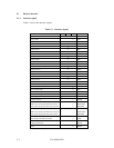
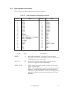
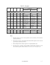
5.2.1 I/O registers
Communication between the host system and the device is done through input-output (I/O)
registers of the device.
These I/O registers can be selected by the coded signals, CS0–, CS1–, and DA0 to DA2 from
the host system. Table 5.3 shows the coding address and the function of I/O registers.