


C141-E090-01EN4 - 2
4.2.2 Head
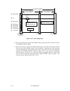
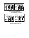
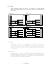
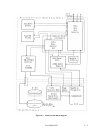
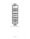
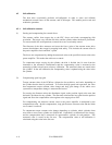
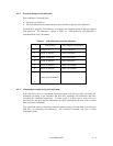
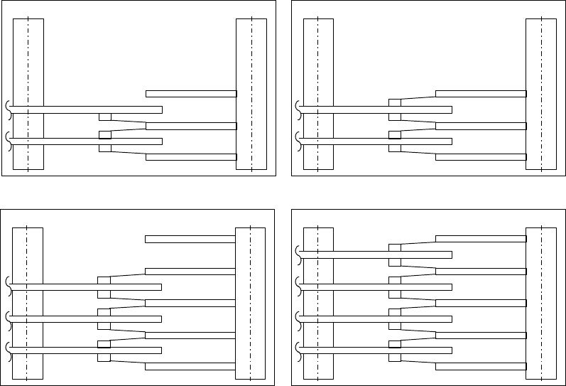
Figure 4.1 shows the read/write head structures. The Numerals 0 to 7 indicate read/write
heads. These heads are raised from the disk surface as the spindle motor approaches the rated
rotation speed.
Spindle
3
2
1
0
Actuator
Spindle
4
3
5
2
1
0
Actuator Spindle
2
1
0
Actuator
4
3
7
6
5
Spindle
2
1
0
Actuator
MPE3136AHMPE3102AH
MPE3273AHMPE3204AH
Figure 4.1 Head structure
4.2.3 Spindle
The spindle consists of a disk stack assembly and spindle motor. The disk stack assembly is
activated by the direct drive sensor-less DC spindle motor, which has a speed of 7,200 rpm.
The spindle is controlled with detecting a PHASE signal generated by counter electromotive
voltage of the spindle motor at starting. After that, the rotational speed is kept with detecting a
servo information.
4.2.4 Actuator
The actuator consists of a voice coil motor (VCM) and a head carriage. The VCM moves the
head carriage along the inner or outer edge of the disk. The head carriage position is
controlled by feeding back the difference of the target position that is detected and reproduced
from the servo information read by the read/write head.