


C141-E090-01EN5 - 10
(6) Cylinder Low register (X'1F4')
The contents of this register indicates low-order 8 bits of the starting cylinder address for any
disk-access.
At the end of a command, the contents of this register are updated to the current cylinder
number.
Under the LBA mode, this register indicates LBA bits 15 to 8.
(7) Cylinder High register (X'1F5')
The contents of this register indicates high-order 8 bits of the disk-access start cylinder
address.
At the end of a command, the contents of this register are updated to the current cylinder
number. The high-order 8 bits of the cylinder address are set to the Cylinder High register.
Under the LBA mode, this register indicates LBA bits 23 to 16.
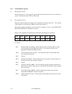
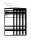
(8) Device/Head register (X'1F6')
The contents of this register indicate the device and the head number.
When executing INITIALIZE DEVICE PARAMETERS command, the contents of this
register defines "the number of heads minus 1".
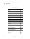
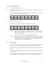
Bit 7 Bit 6 Bit 5 Bit 4 Bit 3 Bit 2 Bit 1 Bit 0
X L X DEV HS3 HS2 HS1 HS0
- Bit 7: Unused
- Bit 6: L. 0 for CHS mode and 1 for LBA mode.
- Bit 5: Unused
- Bit 4: DEV bit. 0 for the master device and 1 for the slave device.
- Bit 3: HS3 CHS mode head address 3 (2
3
). LBA bit 27.
- Bit 2: HS2 CHS mode head address 3 (2
2
). LBA bit 26.
- Bit 1: HS1 CHS mode head address 3 (2
1
). LBA bit 25.
- Bit 0: HS0 CHS mode head address 3 (2
0
). LBA bit 24.