


C141-E090-01EN 4 - 15
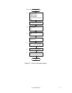
(2) Servo burst capture circuit
The four servo signals can be synchronously detected by the STROB signal, full-wave
rectified integrated.
(3) A/D converter (ADC)
The A/D converter (ADC) receives the servo signals are integrated, converts them to digital,
and transfers the digital signal to the DSP unit.
(4) D/A converter (DAC)
The D/A converter (DAC) converts the VCM drive current value (digital value) calculated by
the DSP unit into analog values and transfers them to the power amplifier.
(5) Power amplifier
The power amplifier feeds currents, corresponding to the DAC output signal voltage to the
VCM.
(6) Spindle motor control circuit
The spindle motor control circuit controls the sensor-less spindle motor. This circuit detects
number of revolution of the motor by the interrupt generated periodically, compares with the
target revolution speed, then flows the current into the motor coil according to the
differentiation (aberration).
(7) Driver circuit
The driver circuit is a power amplitude circuit that receives signals from the spindle motor
control circuit and feeds currents to the spindle motor.
(8) VCM current sense resistor (CSR)
This resistor controls current at the power amplifier by converting the VCM current into
voltage and feeding back.