


DMC-2X00 Chapter 10 Theory of Operation y 141
System Analysis
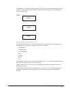
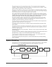
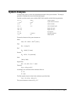
To analyze the system, we start with a block diagram model of the system elements. The analysis
procedure is illustrated in terms of the following example.
Consider a position control system with the DMC-2x00 controller and the following parameters:
K
t
= 0.1 Nm/A Torque constant
J = 2.10
-4
kg.m
2
System moment of inertia
R = 2
Ω
Motor resistance
K
a
= 4 A/V Current amplifier gain
KP = 12.5 Digital filter gain
KD = 245 Digital filter zero
KI = 0 No integrator
N = 500 Counts/rev Encoder line density
T = 1 ms Sample period
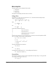
The transfer function of the system elements are:
Motor
M(s) = P/I = Kt/Js2 = 500/s
2
[rad/A]
Amp
K
a
= 4 [Amp/V]
DAC
K
d
= 0.0003 [V/count]
Encoder
K
f
= 4N/2π = 318 [count/rad]
ZOH
2000/(s+2000)
Digital Filter
KP = 12.5, KD = 245, T = 0.001
Therefore,
D(z) = 1030 (z-0.95)/Z
Accordingly, the coefficients of the continuous filter are:
P = 50
D = 0.98
The filter equation may be written in the continuous equivalent form:
G(s) = 50 + 0.98s = .098 (s+51)
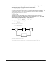
The system elements are shown in Fig. 10.7.