


DMC-2X00 Chapter 3 Connecting Hardware y 45
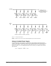
Each input from the auxiliary encoder is a differential line receiver and can accept voltage levels
between +/- 12 volts. The inputs have been configured to accept TTL level signals. To connect TTL
signals, simply connect the signal to the + input and leave the - input disconnected. For other signal
levels, the - input should be connected to a voltage that is ½ of the full voltage range (for example,
connect the - input to 6 volts if the signal is a 0 - 12 volt logic).
Example:
A DMC-2x10 has one auxiliary encoder. This encoder has two inputs (channel A and channel B).
Channel A input is mapped to input 81 and Channel B input is mapped to input 82. To use this input
for 2 TTL signals, the first signal will be connected to AA+ and the second to AB+. AA- and AB-
will be left unconnected. To access this input, use the function @IN[81] and @IN[82].
NOTE: The auxiliary encoder inputs are not available for any axis that is configured for
stepper motor.
TTL Outputs
The DMC-2x00 provides dedicated and general use outputs.
General Use Outputs
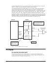
The DMC-2x00 provides eight general use outputs, an output compare and an error signal output. The
general use outputs are TTL and are accessible through the ICM-2900 as OUT1 thru OUT8. These
outputs can be turned On and Off with the commands, SB (Set Bit), CB (Clear Bit), OB (Output Bit),
and OP (Output Port). For more information about these commands, see the Command Summary.
The value of the outputs can be checked with the operand _OP and the function @OUT[] (see Chapter
7, Mathematical Functions and Expressions).
2x80
Controllers with 5 or more axes have an additional eight general use TTL outputs.
NOTE: The ICM-2900 has an option to provide opto-isolation on the outputs. In this case, the user
provides an isolated power supply (+5volts to +24volts and ground). For more information, consult
Galil.
Output Compare
The output compare signal is TTL and is available on the ICM-2900 as CMP. Output compare is
controlled by the position of any of the main encoders on the controller. The output can be
programmed to produce an active low pulse (1usec) based on an incremental encoder value or to
activate once when an axis position has been passed. For further information, see the command OC in
the Command Reference.