


DMC-2X00 Appendices y 157
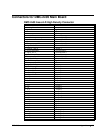
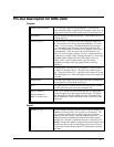
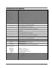
Pin-Out Description for DMC-2x00
Outputs
Analog Motor Command +/- 10 volt range signal for driving amplifier. In servo mode,
motor command output is updated at the controller sample rate. In
the motor off mode, this output is held at the OF command level.
Amp Enable Signal to disable and enable an amplifier. Amp Enable goes low
on Abort and OE1.
PWM/STEP OUT PWM/STEP OUT is used for directly driving power bridges for
DC servo motors or for driving step motor amplifiers. For servo
motors: If you are using a conventional amplifier that accepts a
+/-10 volt analog signal, this pin is not used and should be left
open. The PWM output is available in two formats: Inverter and
Sign Magnitude. In the Inverter mode, the PWM signal is .2%
duty cycle for full negative voltage, 50% for 0 voltage and 99.8%
for full positive voltage (25kHz switching frequency). In the Sign
Magnitude Mode (Jumper SM), the PWM signal is 0% for 0
voltage, 99.6% for full voltage and the sign of the Motor
Command is available at the sign output (50kHz switching
frequency).
PWM/STEP OUT For step motors: The STEP OUT pin produces a series of pulses
for input to a step motor driver. The pulses may either be low or
high. The pulse width is 50%. Upon Reset, the output will be low
if the SM jumper is on. If the SM jumper is not on, the output will
be tristate.
Sign/Direction Used with PWM signal to give the sign of the motor command for
servo amplifiers or direction for step motors.
Error The signal goes low when the position error on any axis exceeds
the value specified by the error limit command, ER.
Output 1-Output 8
Output 9-Output 16
(DMC-2x50 thru 2x80
These 8 TTL outputs are uncommitted and may be designated by
the user to toggle relays and trigger external events. The output
lines are toggled by Set Bit, SB, and Clear Bit, CB, instructions.
The OP instruction is used to define the state of all the bits of the
Output port.
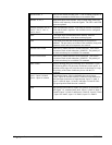
Inputs
Encoder, A+, B+ Position feedback from incremental encoder with two channels in
quadrature, CHA and CHB. The encoder may be analog or TTL.
Any resolution encoder may be used as long as the maximum
frequency does not exceed 12,000,000 quadrature states/sec. The
controller performs quadrature decoding of the encoder signals
resulting in a resolution of quadrature counts (4 x encoder cycles).
NOTE: Encoders that produce outputs in the format of pulses and
direction may also be used by inputting the pulses into CHA and
direction into Channel B and using the CE command to configure
this mode.