


DMC-2X00 Appendices y 177
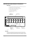
of extended I/O on the controller. Each bank is individually configured as an input or output bank by
inserting the appropriate integrated circuits and resistor packs. The hardware configuration of the
IOM-1964 must match the software configuration of the controller card.
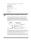
All DMC-2x00 series controllers have general purpose I/O connections. On a DMC-2x10, -2x20, -
2x30, and -2x40 the standard uncommitted I/O consists of: eight optically isolated digital inputs, eight
TTL digital outputs, and eight analog inputs.
The DMC-2x00, however, has an additional 64 digital input/output points than the 16 described above
for a total of 80 input/output points. An 80 pin shielded cable connects from the 80 pin connector of
the DMC-2x00 to the 80 pin high density connector on the IOM-1964 (J5). Illustrations for this
connection can be found on pages 10 and 11.
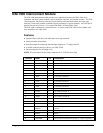
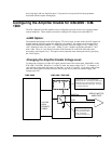
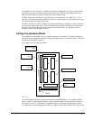
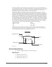
Configuring Hardware Banks
The extended I/O on the DMC-2x00 is configured using the CO command. The banks of buffers on
the IOM-1964 are configured to match by inserting the appropriate IC’s and resistor packs. The layout
of each of the I/O banks is identical.
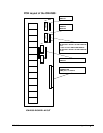
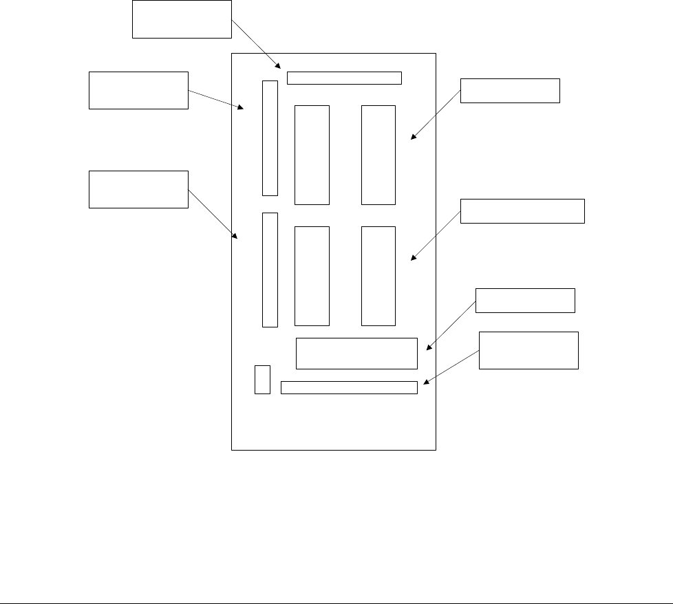
For example, here is the layout of bank 0:
Bank 0
IN
OUT
RP02 OUT
RP04 IN
RP03 OUT
U03 U04
U01 U02
D0
RP01
OUT
C6
17
18
19
20
21
22
23
24
Input Buffer IC's
Output Buffer IC's
Indicator LED's
Resistor Pack for
LED's
Resistor Pack for
outputs
Resistor Pack for
inputs
Resistor Pack for
outputs
Figure A-7
All of the banks have the same configuration pattern as diagrammed above. For example, all banks
have Ux1 and Ux2 output optical isolator IC sockets, labeled in bank 0 as U01 and U02, in bank 1 as
U11 and U12, and so on. Each bank is configured as inputs or outputs by inserting optical isolator
IC’s and resistor packs in the appropriate sockets. A group of eight LED’s indicates the status of each