


DMC-2X00 Appendices y 203
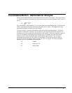
For example, the velocity profile corresponding to the path of Fig. A-21 may be specified in terms of
the vector speed and acceleration.
VS 100000
VA 2000000
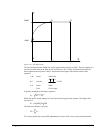
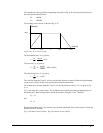
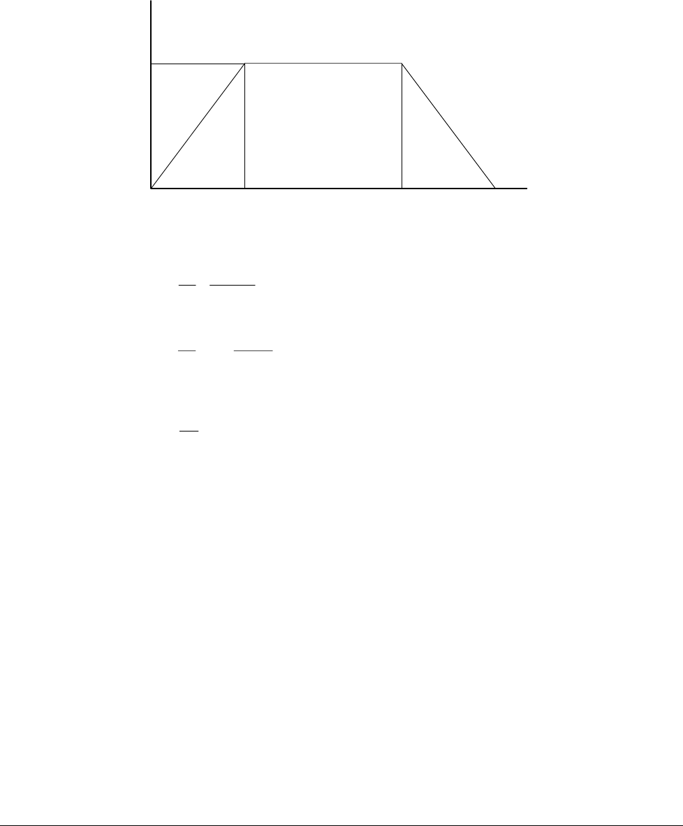
The resulting vector velocity is shown in Fig. A-22.
0.05 0.357
10000
Velocity
time (s)
0.407T
a
T
a
T
s
Figure A-22 - Vector Velocity Profile
The acceleration time, T
a
, is given by
T
V
S
VA
s
a == =
100000
2000000
005.
The slew time, Ts, is given by
The total motion time, Tt, is given by
T
D
V
S
Tsta=+=0 407.
The velocities along the X and Y axes are such that the direction of motion follows the specified path,
yet the vector velocity fits the vector speed and acceleration requirements.
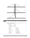
For example, the velocities along the X and Y axes for the path shown in Fig. A-21 are given in Fig.
A-23.
Fig. A-23a shows the vector velocity. It also indicates the position point along the path starting at A
and ending at D. Between the points A and B, the motion is along the Y axis. Therefore,
Vy = Vs
and
Vx = 0
Between the points B and C, the velocities vary gradually and finally, between the points C and D, the
motion is in the X direction.
Fig. A-23b shows X axis velocity. Fig A-23c shows Y axis velocity.
T
D
VS
T
s
s a
= − =
−
35708
100000
0.05 = 0.307