DMC-2X00 Chapter 3 Connecting Hardware y 43
LSCOM
FLSA
External Resistor Needed for
Voltages > +24V
LSCOM
FLSA
External Resistor Needed for
Voltages > +24V
Configuration to source current at
LSCOM terminal and sink
switch
Configuration to sink current at
LSCOM terminal and source
switch
2.2K
2.2K
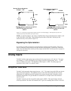
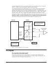
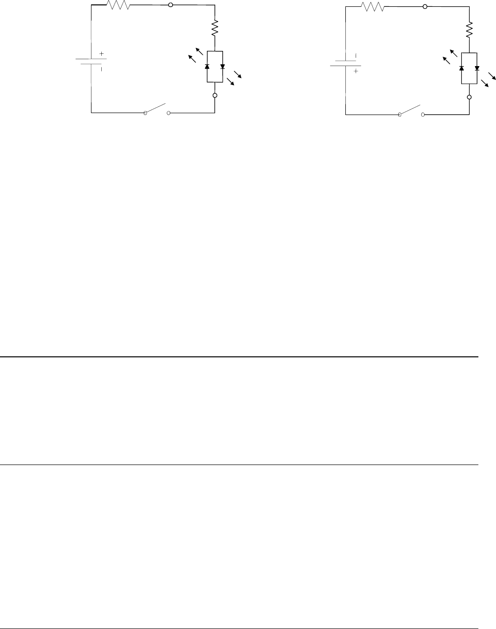
Figure 3-2. Connecting a single Limit or Home Switch to an Isolated Supply. This diagram only shows the
connection for the forward limit switch of the X axis.
NOTE: As stated in Chapter 2, the wiring is simplified when using a Galil Interconnect module, such
as the ICM-1900 or ICM-2900. These boards accept the cables of the DMC-2x00 and provide
terminals for easy access (Refer to figure 2-2).
Bypassing the Opto-Isolation:
If no isolation is needed, the internal 5 volt supply may be used to power the switches. This can be
done by connecting a jumper between the pins LSCOM or INCOM and 5V, labeled JP3 on the main
board. The Galil interconnect modules provide jumpers and the DMC-2x00 also provides a jumper for
making this connection.
Analog Inputs
The DMC-2x00 has eight analog inputs configured for the range between -10V and 10V. The inputs
are decoded by a 12-bit A/D decoder giving a voltage resolution of approximately .005V. A 16-bit
ADC is available as an option. The impedance of these inputs is 10 KΩ. The analog inputs are
specified as AN[x] where x is a number 1 thru 8.
Amplifier Interface
The DMC-2x00 command voltage ranges between +/-10V. This signal, along with GND, provides the
input to the motor amplifiers. The amplifiers must be sized to drive the motors and load. For best
performance, the amplifiers should be configured for a torque (current) mode of operation with no
additional compensation. The gain should be set such that a 10 volt input results in the maximum
required current.
The DMC-2x00 also provides an amplifier enable signal, AMPEN. This signal changes under the
following conditions: the motor-off command, MO, is given, the watchdog timer activates, or the OE1


