


180 • Appendices DMC-2X00
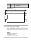
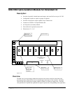
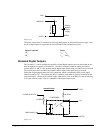
PWROUT
n
OUTC
n
Current
L
o
a
d
External
Isolated
Power
Supply
I/OC
n
V
ISO
GND
ISO
V
pwr
Figure A-12
The power outputs must be connected in a driving configuration as shown on the previous page. Here
are the voltage outputs to expect after the Clear Bit and Set Bit commands are given:
Output Command
Result
CB
n
V
pwr
= V
iso
SB
n
V
pwr
= GND
iso
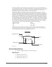
Standard Digital Outputs
The I/O banks 2-7 can be configured as optically isolated digital outputs; however these banks do not
have the high power capacity as in banks 0-1. In order to configure a bank as outputs, the optical
isolator chips Ux1 and Ux2 are inserted, and the digital input isolator chips Ux3 and Ux4 are removed.
The resistor packs RPx2 and RPx3 are inserted, and the input resistor pack RPx4 is removed.
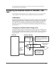
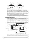
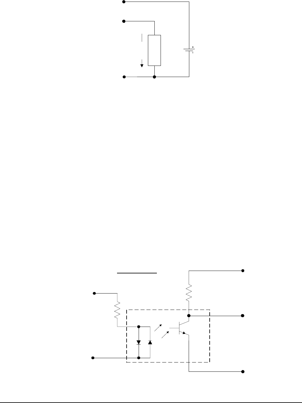
Each bank of eight outputs shares one I/OC connection, which is connected to a DC power supply
between 4 and 28 VDC. The resistor pack RPx3 is optional, used either as a pull up resistor from the
output transistor’s collector to the external supply connected to I/OC or the RPx3 is removed resulting
in an open collector output. Here is a schematic of the digital output circuit:
Internal Pullup
1/4 NEC2505
1/8 RPx3
To DMC-2x40 +5V
DMC-2x40 I/O
I/O
n
I/OC
n
OUTC
n
1/8 RPx2
Figure A-13