


Printer and Troubleshooting Overview 1-3
Theory of Operation
The printer uses an electrophotographic imaging system based on LED array technology.
Two key components of the printer are the image generation system (IGS) controller and
the printer control logic (PCL) board.
Image Generation System (IGS) controller: Each printer is equipped with an IGS con-
troller, which provides the interface between the host computer, the PCL board, LED
printhead, and the disk drives. The controller may be an EIGS or RIGS board.
Printer Control Logic (PCL) board: The PCL board directs the mechanical functions of
the printer and print cycle timing. The PCL board also receives initial machine informa-
tion, such as empty paper cassettes, paper jams, and fuser unit problems.
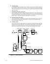
The illustration on the following page details the printing process. The numbers represent
the sequence of events from the time that the system interface receives data, through the
production of a print image, to the preparation for another print.
1 Receiving data
Data from the host is received by the Signal Interface (SI) PCA and is passed to the
Image Generating System (IGS) PCA, which temporarily stores the data in RAM. The
data may consist of information generated on the host computer and sent over the host
communication interface or it may consist of information generated by printer soft-
ware, such as a request for test prints or to print the directory of a diskette.
2 Bit Image
The IGS transforms the host file into a bit map image of 1s and 0s and stores them in
user bitmap RAM. Bitmap memory is nothing more than an electronic piece of paper.
3 Charging the photoconductor belt
When the IGS controller has a full page of data, it causes the PCL board to turn on the
main motor, which rotates the photoconductor belt. As the photoconductor belt
rotates, the main charger applies a high negative charge to it, which repels toner from
the photoconductor belt except in the areas to print.
4 Exposing the image
The negatively charged belt then passes the LED printhead, where the IGS controller
turns the LEDs on and off to discharge the areas of the belt at a density of 300 dots per
inch. The 1s in the bitmap memory turn the LEDs on; 0s turn the LEDs off. The dis-
charged areas create a latent mirror image of the print on the photoconductor belt.
5 Developing the image
As the photoconductor belt continues to rotate, it brings the latent image to the devel-
oper unit. A negative developer bias is applied to toner and the toner is transferred to
the surface of the photoconductor belt. The negatively charged toner (which clings to
small metal carrier beads) is attracted to the discharged areas of the belt. The carrier
beads do not transfer. The belt, with the developed image on its surface, rotates out of
the developer unit. At this time you can remove the photoconductor belt and read what
is printed on it, which you may need to do when troubleshooting print problems.