


6-22 Wiring Diagrams and Electrical Data
Host Interface Reference
Standard printers support three host interfaces: RS-232C, RS-422, and Centronics Parallel.
User-level information about the installation, configuration, and use of these interfaces is
included in the printer’s Guide to Operations.
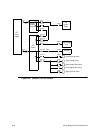
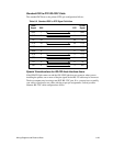
RS-232C Host Interface
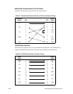
A printer is standard data terminal equipment (DTE), designed specifically for a direct
connection to a standard data communication equipment (DCE) host. The standard signal
definitions for DTE to DCE equipment are outlined in the table that follows.
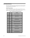
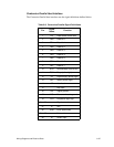
Table 6-1. RS-232C DCE to DTE Signal Definitions
Pin
Signal
Name
Function
1 FG Frame or chassis ground
2 TD Transmitted data
3 RD Received data
4 RST Request to send
5 CTS Clear to send
6 DSR Data set ready
7 SG Signal ground
8 DCD Data carrier detect
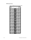
9 Positive DC test voltage
10 Negative DC test voltage (unassigned)
11 (S)DCD Secondary data carrier detect
12 (S)CTS Secondary clear to send
13 (S)CTS Secondary clear to send
14 (S)TD Secondary transmitted data
15 TC Transmitter clock
16 (S)RD Secondary received data
17 RC Receiver clock
18 RDC Receiver debit clock
19 (S)RTS Secondary receive to send
20 DTR Data terminal ready
21 SQ Signal quality detect
22 RI Ring indicator
23 DRS Data rate select
24 (TC) External transmitter clock
25 BSY Busy