


Options 8-7
Input Control Board Logic
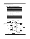
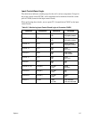
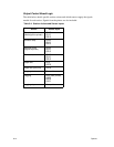
The table below indicates switching logic for the unit’s various components. Except for
the power control switch (PCSW), each component can be monitored from the various
pins of CN508 (located on the input control board).
When performing these checks, use test point TP 1 (located below CN507 on the input
control board).
Table 8-2. Monitoring Input Control Board Logic at Connector CN508
Connector Component Monitored Condition
CN508-4 PHS High
Low
Paper present
No paper present
CN508-13 PES High
Low
Paper present
No paper present
CN508-19 IPES High
Low
Paper present
No paper present
CN508-16 IULS High
Low
Limit
No Limit
CN508-21 DSW High
Low
Door open
Door closed
CN508-10 ILLS High
Low
Limit
No Limit
CN508-2 NPS High
Low
ON
Off
CN508-25, 26 IPM (M2) +12 Vdc
0 Vdc
Feed
No feed
CN508-23 IEM (M1) +12 Vdc
0 Vdc
Up
Off
CN508-24 IEM (M1) +12 Vdc
0 Vdc
Down
Off
CN507-2 PCSW 0 Vdc
+12 Vdc
Unit mounted
Unit not mounted