


116 Chapter4
Field Replaceable Units
FRU Removal and Replacement
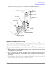
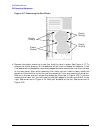
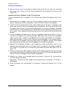
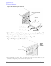
6. Remove the fan from the bracket by slightly pulling the left and right fan mounting
clips away from the fan, and then pulling outward in the direction of the arrow. See
Figure 4-21.
Installing a Fan or Speaker in the I/O Card Area
If you are replacing a fan or speaker in the I/O card area, follow the steps covered in this
section.
1. Remove the fan or speaker from the I/O card area by following the procedure in the
section “Removing the Fan and Speaker from the I/O Card Area” in this chapter.
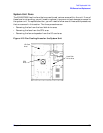
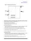
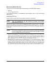
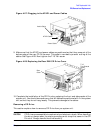
2. Install the fan by positioning the fan power cable channel so that it is located in the
lower right corner of the fan and speaker mounting bracket. See Figure 4-20. Note that
the power cable channel must be positioned against the mounting bracket. Once you
have the fan in the correct position, pull outward on the fan mounting clips and put the
fan in place. Then release the mounting clips so that they hold the fan on the mounting
bracket.
3. Install the speaker by positioning it so that the speaker cable can be easily run out of
the hole in the back of the mounting bracket. See Figure 4-20. Note that the speaker
cable must be held in place on the backside of the mounting bracket by the speaker
cable clips as shown in Figure 4-20. Once you have the speaker in the correct position,
pull outward on the speaker mounting clips and put the speaker in place. Then release
the mounting clips so that they hold the speaker on the mounting bracket.
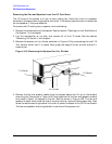
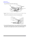
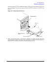
4. Replace the fan/speaker bracket in the chassis by inserting the bottom and in first
between the system board and the CD cage. Insert the edge into the slots provided an
then rotate it into place until the mounting clip snaps into place. See Figure 4-20. on
page 115.
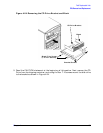
5. Position the fan power cable, speaker cable and LCD ribbon cable so that they run along
the system board side of the computer chassis. See Figure 4-20. Dress the cables so that
they are free from damage by other system components.
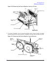
6. Place the air divider into its proper position as shown in Figure 4-19., and screw the
T-15 Torx screws into place.
7. Replace all I/O cards into their proper slots as explained in the section “I/O Cards” in
this chapter.
8. Close the system unit as discussed in the section “Closing the System Unit” in this
chapter.