


Chapter 4 141
Field Replaceable Units
FRU Removal and Replacement
DIMM Cards
This section contains information regarding the installation and removal of memory
(DIMM cards). Before continuing with this section, carefully read the following list of
considerations:
• Use the procedure described in “Displaying the Current Memory Configuration” on
page 175 before attempting to install additional memory DIMMs in the workstation.
• Review the steps involved in installing memory DIMMs before you begin.
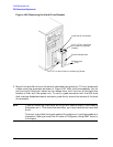
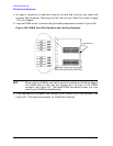
• Insert DIMMs in the order shown. Please refer to Figure 4-56.
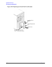
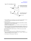
• Note the proper orientation for DIMMs when inserting them into their connectors
because the connectors are keyed to prevent backwards installation. See Figure 4-57.
• Use the “Boot Console Handler” to verify that the computer recognizes the additional
DIMMs when you have finished installation.
Installing Additional Memory
Perform the following steps to add memory (DIMM cards) to the workstation.
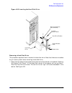
1. Open the side panel of the system unit as explained in the section “Opening the Left
Side Panel of the System Unit” of this chapter.
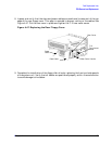
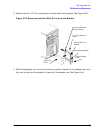
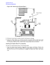
2. Lay the system on its side as shown in Figure 4-55. The memory slots should be aligned
as shown in Figure 4-57. Figure 4-56. provides the loading sequence for the DIMM
cards. Currently the B1000 and C3000 workstations use 128 Mbyte and 256 Mbyte
DIMM cards. Note that the DIMM cards do not have to be loaded in pairs.
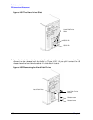
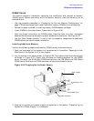
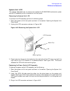
Figure 4-55. Propping Up the Power Supply
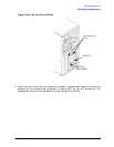
3. Prop up the system unit power supply as explained in the section “Propping Up the
System Unit Power Supply” in this chapter.
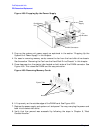
Power Supply
Disk/Memory Fan
DIMM Card
DIMM Connector