


126 Chapter4
Field Replaceable Units
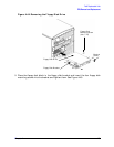
FRU Removal and Replacement
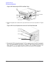
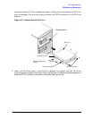
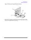
Figure 4-35. Removing the Floppy Disk’s Rear Cover
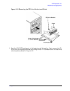
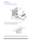
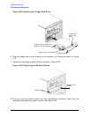
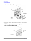
3. Rotate the system unit around until you see the front of the workstation as shown in
Figure 4-36.
Figure 4-36. Front of Workstation with the Front Panel Removed
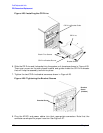
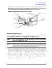
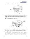
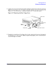
4. Remove both floppy disk bracket screws (T-15 Torx screws) and pull the floppy disk
bracket out of the chassis assembly as shown in Figure 4-37. Next remove the four
floppy disk blank screws (T-10 Torx screws) as shown in Figure 4-37. and remove the
blank from the bracket. You are now ready to mount the floppy disk drive into the
floppy disk bracket.
Rear Cover
Rear Cover
Handle
T-15
Torx/slotted
Screw
Power Cable
Floppy Data Cable
LCD
Power Switch
CD Drive
Blank
Floppy Drive
Bank