


Chapter 4 133
Field Replaceable Units
FRU Removal and Replacement
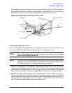
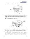
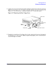
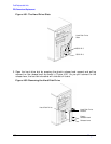
8. Inspect and verify that the data and power cables are positioned to come out of the top
edge of the rear floppy cover. This edge is rounded to prevent cutting of the cables. See
Figure 4-47. Put the rear cover in place and tighten the T-15 rear cover screw.
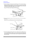
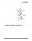
Figure 4-47. Replacing the Rear Floppy Cover
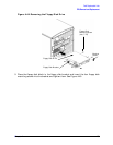
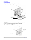
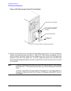
9. Complete the installation of the floppy disk drive by replacing the front and side panels
of the system unit. Verify that all cables are positioned properly within the workstation
to avoid damage to the cables.
Rear Cover
T-15
Torx/slotted
Screw
Rear Cover HandleData Cable
Power
Cable