


Chapter 4 125
Field Replaceable Units
FRU Removal and Replacement
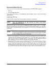
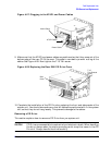
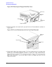
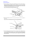
cover’s edge is rounded to keep you from cutting the cables. Figure 4-34. Next, place the
end opposite the rear cover handle into the cover slot and tighten the T-15 Torx screw to
secure the rear cover. You have now completed the removal of the CD Drive.
Figure 4-34. Replacing the CD Drive Rear Cover
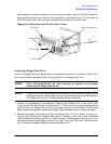
Installing a Floppy Disk Drive
Install the floppy disk drive by following the procedure covered in this section. Note there
are no jumper settings required for the installation of the floppy disk drive.
WARNING
Turn the workstation off and unplug the power cord before
installing the floppy disk drive.
CAUTION
Floppy disk drives are susceptible to mechanical and electronic shock. When
handling the drive, always wear the static-grounding wrist strap that came in
the Floppy disk drive kit. Always handle the drive carefully.
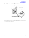
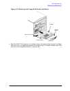
1. Perform the procedures in the sections “Opening the System Unit Front Panel” and
“Opening the Left Side Panel of the System Unit.” The front panel needs to be opened so
you can insert the floppy disk drive into its proper location in the chassis. The left side
panel needs to be opened to access the floppy’s data connector and its power connector.
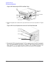
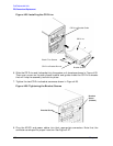
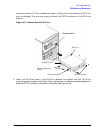
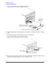
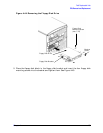
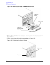
2. Remove the floppy rear-disk cover by unscrewing the T-15 Torx screw as shown in
Figure 4-35. Note that the floppy’s rear cover is located on the rear of the removable
media chassis inside the system unit. Push the cover handle away from the rear of the
removable media chassis approximately one inch. Next pull the cover handle toward
you. The data and power cables are now accessible to you.
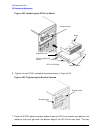
Rear Cover Handle
Rear Cover
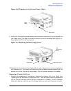
Audio Cable
ATAPI Cable
Power Cable
T-15
Torx/slotted
Screw